FTTH ODN Components Overview
By Jergeo Engineering Team | Updated August 2026 · 12 min read

Every FTTH network is built from the same set of passive components. Fiber leaves the central office, gets routed through a series of cabinets and closures, split into smaller groups, and eventually reaches a box on the wall outside someone's home. The FTTH network architecture defines where each piece goes, but the physical components that make it happen — the ODN components — are what this article covers.
If you're procuring for a deployment project, the component list is the first document you build. Get it wrong — missing a component type, or spec'ing the wrong capacity — and you'll find out during installation, not during planning. That's the expensive kind of lesson.
Summary
The ODN (Optical Distribution Network) consists of seven core passive components: Optical Distribution Frame (ODF) at the central office, Fiber Distribution Cabinet (FDC) at the distribution layer, Fiber Termination Boxes at the access point, Splice Closures for cable joints, PLC Splitters for signal division, Fiber Patch Panels for indoor cross-connects, and Patch Cords / Pigtails for interconnection. Together, these form the complete optical path from OLT to ONT in a PON network, with a designed lifespan of 20-25 years.
What is the ODN in an FTTH network
The ODN — Optical Distribution Network — is defined in ITU-T G.984 as the passive optical infrastructure between the OLT (Optical Line Terminal) at the central office and the ONT (Optical Network Terminal) at the subscriber's premises. It includes everything except the active electronics: fiber cables, connectors, splices, splitters, and the enclosures that house them. (Source: ITU-T G.984)
In a typical GPON deployment, the ODN carries a single downstream wavelength (1490 nm) and upstream wavelength (1310 nm), with an optional 1550 nm video overlay. The optical power budget — the total loss the link can tolerate — is shared across every component in the path. Each connector adds ~0.3 dB loss, each splice adds ~0.1 dB, and the PLC splitter adds the most: 10.5 dB for a 1:32 split, 13.8 dB for 1:64.
This matters because the ODN is a budget game. Every component you add has an optical cost. Understanding what each component does — and how much loss it introduces — is essential for link planning.
FTTH ODN network architecture: from OLT to ONT
A standard FTTH ODN follows a three-segment topology: feeder, distribution, and drop. Each segment has specific components assigned to it.
Segment 1: Feeder (central office to distribution point)
The feeder segment runs from the OLT's optical output to the first distribution point — usually a street cabinet or a manhole enclosure. This is the longest segment, typically 5-20 km, using high-fiber-count cables (144-576 fibers). The ODF at the central office provides the patch point between the OLT equipment and the feeder cable.
- Components: ODF, feeder cable, splice closures (if cable joints are needed)
- Fiber count: 144-576 fibers depending on subscriber density
- Typical distance: 5-20 km
Segment 2: Distribution (distribution point to access point)
At the distribution point, fibers are split into smaller groups using PLC splitters housed in an FDC. The FDC is the workhorse of this segment — it terminates the feeder cable, houses the splitters, and provides patching to distribution cables. A typical FDC serves 4-32 distribution cables, each carrying 4-24 fibers.
- Components: FDC (with PLC splitters), distribution cables, splice closures
- Fiber count: 4-24 fibers per distribution cable
- Typical distance: 500 m - 5 km
Segment 3: Drop (access point to subscriber)
The drop segment connects the last access point — a fiber termination box on a pole, pedestal, or building wall — to the subscriber's ONT. Drop cables are typically single-fiber or 2-fiber cables (G.657A2 bend-insensitive fiber) running 10-200 meters from the termination box to the home.
- Components: Fiber termination box, drop cable, optional connector panel inside the home
- Fiber count: 1-2 fibers per subscriber
- Typical distance: 10-200 m
Core ODN components explained
Here's a component-by-component breakdown of every piece of passive infrastructure in a standard FTTH ODN, in order from central office to subscriber.
1. ODF (Optical Distribution Frame)
The ODF sits in the central office or equipment room. It's the first point where the OLT's fiber outputs are organized and patched to outgoing feeder cables. An ODF is a high-capacity, rack-mounted or floor-standing frame that can hold 96-720+ ports with integrated splice trays and adapter panels.
The ODF's job is straightforward: provide a structured, labeled, and protected termination point for the most critical fibers in the network. Every subscriber in the service area passes through the ODF at some point. If the ODF is poorly organized — no labeling, no slack storage, wrong connector types — every maintenance visit becomes a troubleshooting expedition.
Key specs to check: port capacity, rack compatibility (19" standard), adapter type (typically LC or SC), and whether it includes splice tray slots for feeder cable termination. The ODF vs patch panel comparison covers when you need a full ODF versus a simpler patch panel.
2. FDC (Fiber Distribution Cabinet)
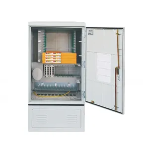
The FDC is the distribution layer's main enclosure. It's a floor-standing, wall-mount, or pole-mount cabinet installed at the street level, housing PLC splitters, splice trays, and patch panels in a weatherproof enclosure. Capacity ranges from 72 to 1,152 ports depending on the model.
In practice, the FDC is where the network topology gets complex. Feeder cables enter from one side, get terminated in splice trays. PLC splitters sit in dedicated slots. Distribution cables exit from the other side. A single FDC can serve 200-500 subscribers when loaded with 1:32 splitters.
What matters in FDC selection: IP rating (IP65 minimum for outdoor), material (SMC for most deployments — lighter, corrosion-proof, and handles UV better than steel), port capacity with 20% growth headroom, and cable entry configuration. We've seen projects where the FDC was specified with bottom cable entry but the site had all cables coming from above — simple mistake, but it meant on-site modifications during installation.
For detailed specs and selection criteria, the FDC buying guide covers capacity planning, material comparison (SMC vs steel vs ABS), and IP rating requirements.
3. PLC Splitter (Planar Lightwave Circuit Splitter)
The PLC splitter divides one optical signal into multiple outputs. In FTTH networks, common configurations are 1:8, 1:16, 1:32, and 1:64. Each split level adds insertion loss: ~7 dB for 1:8, ~10.5 dB for 1:32, ~13.8 dB for 1:64. This is the single largest source of optical loss in the ODN.
PLC splitters come in two form factors for ODN deployment:
- Bare fiber splitter: installed inside FDCs or splice closures, pigtails spliced to network fibers
- Cassette/mini-module: plug-in form factor for FDCs with dedicated splitter slots, uses connectorized pigtails
The splitter is the component that determines your network's splitting architecture — centralized splitting (all splitters in one location) or distributed splitting (splitters at multiple points). Most GPON deployments use centralized 1:32 splitting in a single FDC for simplicity, but some large FTTH networks use a two-stage approach (1:4 + 1:8 = 1:32) to reduce the cable count at the central office.
For splitter selection details, the PLC splitter guide covers types, ratios, insertion loss, and cassette form factors.
4. Splice Closure
Splice closures protect fiber splices in outside plant cables. They come in two main types: dome (vertical, used for vertical cable entries on poles) and inline/horizontal (for horizontal cable runs along ducts or underground). Capacity ranges from 48 to 288+ fiber splices per closure.
In an FTTH ODN, splice closures appear wherever cable segments need to be joined — between the feeder and distribution cables, at mid-span branching points, or where cable lengths exceed manufacturing limits. A single FTTH deployment might use hundreds of closures across the network.
Critical specs: sealing method (heat shrink, mechanical compression, or gel-filled), IP rating (IP68 for buried installations), fiber capacity, and whether it has enough splice tray slots for your configuration. Heat shrink sealing is the most common method — it's reliable but requires a heat gun on-site. Gel-filled closures are faster to install but more expensive per unit.
The splice closure selection guide covers dome vs inline types, sealing methods, and capacity planning in detail.
5. Fiber Termination Box
The fiber termination box is the last enclosure before the subscriber's drop cable. It's a compact wall-mount, pole-mount, or pedestal-mount box that terminates the distribution cable and provides adapter ports (usually 2-24 ports) for connecting drop cables. SC adapters are standard in FTTH.
Think of it as a mini-distribution point. The distribution cable enters the box, gets terminated on splice trays or direct adapter mount, and each subscriber connects via a short patch cord from the box's adapter to their drop cable.
Key selection factors: port count, IP rating (IP54 minimum for outdoor wall-mount, IP65 for exposed locations), material (ABS for indoor, SMC or PC for outdoor), and whether it includes a splitter slot for in-box splitting. The termination box selection guide covers port capacity, IP rating options, and connector types for different deployment scenarios.
6. Fiber Patch Panel
Fiber patch panels handle indoor cross-connections and terminations. They're rack-mount (1U-6U) or wall-mount units with adapter panels on the front and splice trays or slack storage inside. Typical capacity: 12-144 ports.
In the ODN context, patch panels serve two roles: as the indoor ODF substitute in smaller central offices, and as the building entry point in MDU (Multi-Dwelling Unit) FTTH deployments. In an MDU, a patch panel in the basement terminates the distribution cable, and individual drop cables run to each apartment through conduit.
Unlike FDCs, patch panels are not weatherproof. They belong in controlled environments — equipment rooms, telecom closets, or basements. If you need outdoor protection, use an FDC or outdoor-rated termination box instead. The fiber distribution panel selection guide covers the decision points for indoor panels.
7. Patch Cords and Pigtails
Patch cords are the jumper fibers that connect adapter ports between equipment and panels. Pigtails are single-ended fibers with a connector on one end and bare fiber on the other, spliced to the network cable inside a panel or closure.
In an FTTH ODN, pigtails appear everywhere cables meet panels: inside the ODF, FDC, splice closure, and termination box. Patch cords are used for temporary or reconfigurable connections — between a panel port and an OLT, or between a panel and a test set.
Connector types must match throughout the chain. SC-SC pigtails for FTTH networks, LC-LC for data center and enterprise environments. Mixed connector types require adapters, and every adapter adds 0.2-0.5 dB of insertion loss. Connector contamination at these interfaces is the number one cause of field link failures, according to the FOA (Source: FOA Guide to Fiber Optic Installation).
Component placement in the FTTH ODN
Here's how the components map to the physical network:
| Segment | Components | Location | Typical Capacity |
|---|---|---|---|
| Central Office | ODF, Patch cords | Equipment room, indoor | 96-720 ports |
| Feeder | Feeder cable, Splice closures | Underground duct, aerial, or buried | 144-576 fibers |
| Distribution Point | FDC, PLC splitters, Patch panels | Street cabinet, pole, or equipment room | 72-1152 ports |
| Distribution | Distribution cable, Splice closures | Aerial, buried, or duct | 4-24 fibers per cable |
| Access Point | Fiber termination box | Pole, wall, or pedestal | 2-24 ports |
| Drop | Drop cable, Connector (indoor panel) | Aerial, facade, or indoor conduit | 1-2 fibers per subscriber |
This table simplifies the reality. Some deployments merge segments — for example, placing the splitter directly inside the termination box instead of the FDC. Others add intermediate distribution frames for very large networks. But the core component set stays the same.
Selection criteria for ODN components
When building a component list for an FTTH project, six factors drive every selection decision.
Environmental rating
The installation location determines the IP rating. Outdoor components need IP65 (FDCs, outdoor termination boxes) or IP68 (buried splice closures). Indoor components need IP20 minimum. We've seen cost savings attempts where IP54-rated boxes were installed in locations that needed IP65 — and then the boxes failed during the first heavy rain. The cost of replacing failed components and dispatching crews to a live network is always more than the difference between IP54 and IP65 hardware.
Capacity with growth margin
Plan for 15-20% spare capacity at every node. An FDC with 144 ports should be loaded to 120 ports maximum. A termination box with 8 ports should only have 6 subscribers connected initially. The cost difference between an 8-port and 12-port termination box is small. The cost of replacing an undersized box in a live network — truck roll, labor, service disruption — is not.
Connector standardization
Pick one connector type for the entire ODN and stick with it. SC is standard for FTTH. LC is standard for data center and enterprise. Mixing connector types across the network creates adapter chains that add loss, cost, and failure points. The connector contamination guide explains why every additional connection point is a potential failure.
Material durability
For outdoor enclosures, SMC (Sheet Molding Compound) is the standard choice — UV resistant, corrosion-proof, lightweight, and durable in temperatures from -40°C to +65°C. Stainless steel is used where mechanical impact resistance is critical (vandal-prone locations, areas with vehicular traffic near poles). ABS is acceptable for indoor enclosures only. The cabinet materials comparison covers weight, lifespan, and cost differences between these materials.
Optical budget impact
Every component in the ODN adds loss. For a GPON Class B+ link with a 28 dB budget, a 1:32 splitter uses 10.5 dB. That leaves 17.5 dB for everything else — connectors, splices, and fiber attenuation. A typical FTTH link uses 2-4 connectors (0.6-1.2 dB), 4-8 splices (0.4-0.8 dB), and 15 km of fiber at 0.35 dB/km (5.25 dB). Total: ~8 dB. That leaves margin. But if you add unnecessary components — extra patch points, unneeded adapters — you eat into that margin.
Installation access
Consider how technicians will access each component during installation and maintenance. FDCs need clearance for door opening and fiber routing. Splice closures need enough space around them for a technician to work. Termination boxes mounted at height need safe ladder access. If the component is hard to reach, maintenance gets skipped or done poorly. This is a design problem, not a technician problem.
Common mistakes in ODN component specification
Under-sizing the FDC
Specifying an FDC with exactly the number of ports needed for the initial subscriber count — with no growth margin. Within 12-18 months, new subscribers arrive and the FDC is full. Adding a second FDC next to the first is expensive and ugly. The right answer is to spec the FDC for the projected 3-year subscriber count, and load splitters progressively as demand grows.
Ignoring sealing on splice closures
Heat shrink sealing is the most common method, but it requires a heat gun and careful technique. In humid or rainy conditions, field technicians sometimes skip proper heat shrink application. The closure looks sealed, but water slowly wicks in over months, causing fiber degradation that shows up as intermittent link failures. Gel-filled closures eliminate this risk but cost more per unit. For projects in wet climates, gel-filled closures pay for themselves in reduced truck rolls.
Mixing connector types
An FDC with SC adapters receiving LC patch cords from the distribution cables. Or a termination box with FC adapters in an SC-based network. This happens when procurement orders components from different suppliers without checking connector compatibility. The fix — adapter converters — adds 0.3-0.5 dB loss per conversion and introduces another contamination point. Always verify connector type consistency across the entire component list before ordering.
Forgetting cable management
Specifying components with enough ports but not enough slack storage or fiber routing channels. When a technician opens a packed FDC with no room to route new fibers, they have to move existing fibers to make space. Every move risks bending a fiber past its minimum radius or disconnecting a live subscriber. Slack storage is not a "nice to have" — it's a requirement for any component that will be maintained by field technicians over 20+ years.
References
- FOA Guide to Fiber Optic Installation — The Fiber Optic Association reference on installation practices, connector handling, and field testing
- ITU-T G.657 — Characteristics of bending-loss insensitive single-mode fiber for access networks
Related Products
JFDC-144A Fiber Distribution Cabinet
144-port outdoor cabinet for FTTH distribution networks
View Product →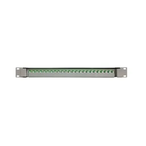
JODF-U3A Optical Patch Panel
Sliding-type rack-mount panel with rotary fiber management
View Product →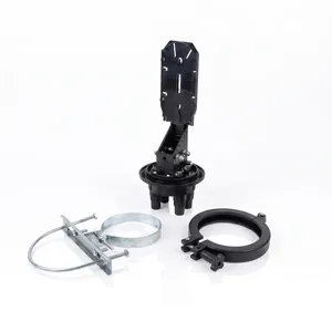
JFSC-L144A Fiber Splice Closure
144-core horizontal closure for outside plant fiber splicing
View Product →Related Articles
FTTH Network Architecture: From OLT to ONT
ODN hierarchy, feeder/distribution/drop segments, splitter placement, and deployment topologies explained.
Read Article →
ODN Equipment Guide: Complete Component List
Full list of ODN equipment: FDC, FDB, FSC, OTB, ODF, PLC splitters — function, specs, and selection criteria.
Read Article →
Fiber Splice Closure Guide: Dome vs Inline
Dome vs inline closures, capacity selection, sealing methods, and IP68 protection explained.
Read Article →