Fiber Optic Bend Radius: The Installation Mistake That Costs You dB
By Jergeo Engineering Team | Updated September 2026 · 10 min read
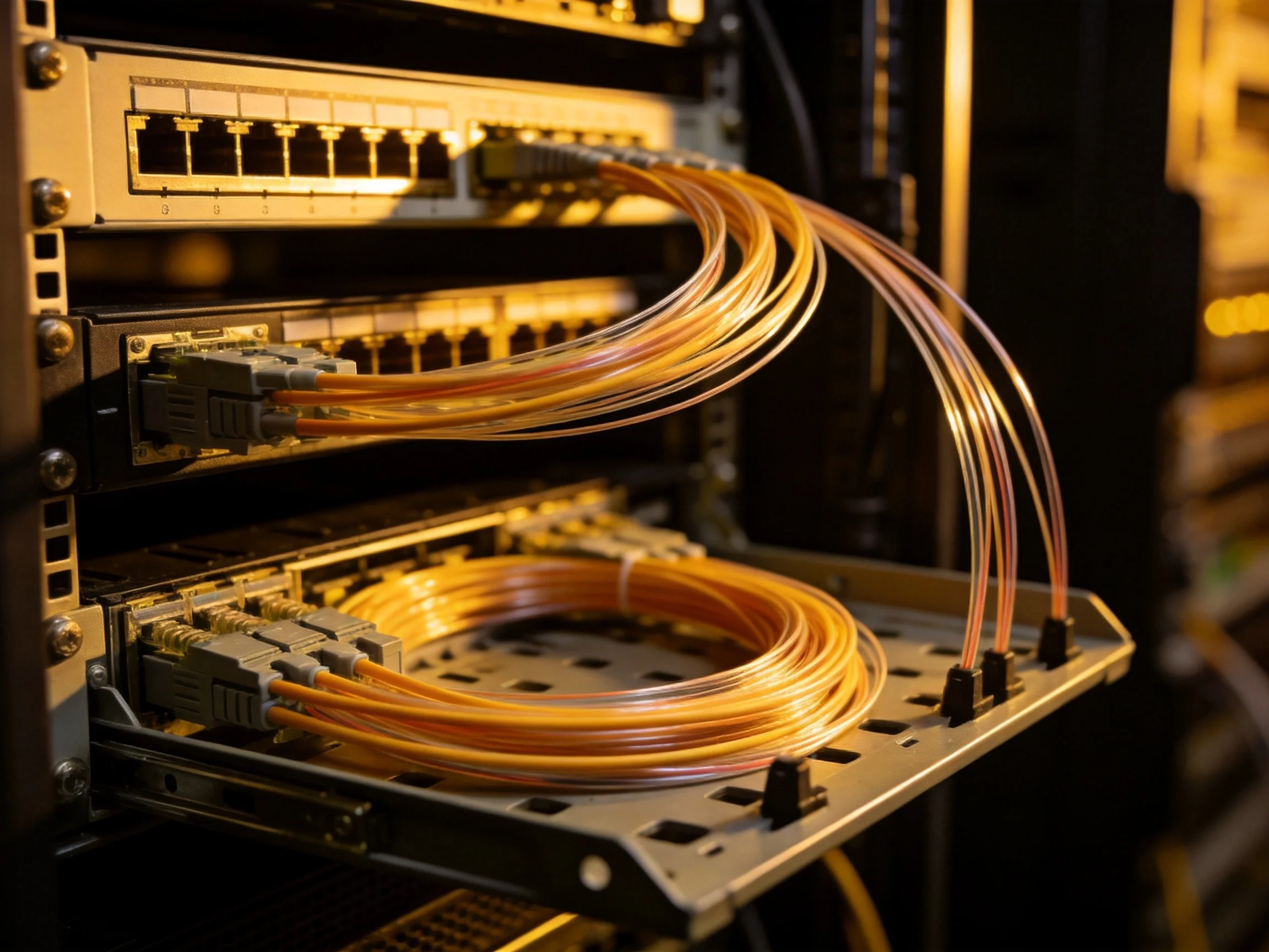
Every fiber optic field fault we have investigated in the past two years traces back to the same root cause: someone bent the fiber tighter than they should have. Not in the backbone cable run — that part usually gets handled correctly because the cable is stiff and obviously resistant to tight bends. The problem happens inside the enclosure. At the fiber distribution cabinet, at the patch panel, inside the splice tray. That is where bare fiber gets coiled, tucked, and stuffed into whatever space is available.
And that is where bend radius violations silently destroy your link budget. A 10 mm bend in standard single-mode fiber does not break the fiber — it just adds 3 to 5 dB of loss per bend. The link still passes the OTDR test on day one because the margin covers it. But as temperature cycles, vibration accumulates, and the coating degrades, that marginal link becomes a failing link. Six months later, the customer calls about intermittent packet loss, and nobody suspects the tight fiber loop hidden behind a splice tray.
Summary
Fiber optic bend radius is the minimum curvature a fiber can sustain without measurable signal loss. For standard single-mode fiber (G.652.D), the long-term minimum is 15 mm; for bend-insensitive fiber (G.657.A1/A2), it drops to 7.5 mm. But the fiber itself is only half the equation — the enclosure design (FDC trays, patch panel routing channels, splice storage) determines whether the installed fiber actually respects that radius. This article breaks down the physics of bend loss, the real installation numbers, and how enclosure design either prevents or enables the most common fiber optic installation mistake.
Why Bend Radius Matters More Than You Think
Light travels through the fiber core by total internal reflection — it bounces off the boundary between the core (higher refractive index) and the cladding (lower refractive index). When the fiber bends, the angle of incidence at the core-cladding boundary changes. Below a certain radius, some light rays no longer satisfy the total internal reflection condition and leak out through the cladding. This is macrobend loss.
The key thing to understand: macrobend loss is not a sudden failure. It is a gradual increase in attenuation that depends on three variables:
- Bend radius — smaller radius means exponentially higher loss. Going from 30 mm to 15 mm does not double the loss; it increases it by 10 to 100 times depending on fiber type.
- Wavelength — longer wavelengths are more sensitive to bending. A fiber that shows no measurable loss at 1310 nm may show 0.5 dB loss at 1550 nm when bent to the same radius. This matters because 1550 nm is where your highest-capacity DWDM channels operate.
- Duration — sustained bends cause more loss than temporary bends. The fiber coating deforms under constant pressure, pushing the glass closer to the bend constraint. This is why a fiber that tests fine during installation can develop excess loss months later.
For a PON network operating at 1490 nm (downstream) and 1550 nm (RF video overlay), bend-induced loss directly reduces the optical power budget available for split ratio and distance. If your link budget has 28 dB of margin and you lose 2 dB to bend violations across multiple closures, you have effectively reduced your splitter capacity by one full split stage — going from 1:64 to 1:32 without changing any active equipment.
The Numbers: Installation vs. Long-Term Bend Radius
The fiber optic bend radius spec exists in two flavors, and confusing them is where most installation errors begin.
Standard Single-Mode Fiber (ITU-T G.652.D)
- Short-term (installation) bend radius: 30 mm — applies during pulling, routing, and splicing. The fiber is under mechanical stress, so the minimum radius is larger to prevent immediate damage.
- Long-term (in-service) bend radius: 15 mm — applies once the fiber is fixed in place inside a tray, panel, or enclosure. The fiber is at rest, but sustained pressure from the coating and surrounding fibers can still cause gradual loss increase.
- For cable (not bare fiber): Typically 10x cable OD for long-term, 20x cable OD for installation. A 12 mm diameter cable needs 120 mm long-term radius and 240 mm during pulling.
Bend-Insensitive Fiber (ITU-T G.657.A1/A2)
- G.657.A1: Short-term 10 mm, long-term 7.5 mm. Compatible with G.652.D for splicing — same mode field diameter. Most common choice for FTTH drop cables and indoor distribution.
- G.657.A2: Same bend performance as A1, but with tighter splicing compatibility. Slightly larger mode field diameter difference from G.652.D means splice loss may be 0.05-0.1 dB higher at each junction.
- G.657.B2/B3: Short-term 5 mm, long-term 5 mm. Extreme bend tolerance, but not splice-compatible with G.652.D. Used only in specialized indoor applications where tight routing is unavoidable.
The practical implication for field deployment: even with G.657 fiber, you cannot just stuff fibers anywhere. The 7.5 mm long-term radius means a fiber can survive a tight bend, but it does not mean it should be held at that radius indefinitely. The enclosure still needs to provide adequate space.
Where Bend Radius Violations Actually Happen
The fiber run from the central office to the distribution point rarely has bend radius problems. The cable is thick, stiff, and installed by crews who know to avoid kinks. The violations happen at three specific points in the network, all involving enclosures.
1. Inside the Fiber Distribution Cabinet (FDC)
The FDC is the most common violation point because it has the highest fiber density. A 288-port JFDC-288A holds 288 individual fiber connections plus their splice protection sleeves and drop cable loops. That is a lot of fiber packed into a relatively small enclosure.
What we see in the field:
- Splice tray overfilling — the tray is rated for 12 or 24 splices, but the installer forces 30+ splices in, creating fiber loops that press against the tray walls at sub-minimum radius.
- Drop cable coiling — excess drop cable gets stuffed into the cabinet without a dedicated storage area, creating tight loops between the cable entry gland and the adapter panel.
- Routing channel bypass — the cabinet has fiber routing channels designed to maintain bend radius, but the installer ignores them and runs fibers directly across the cabinet, creating uncontrolled bends.
The fix is partly training and partly design. The JFDC-576A and JFDC-1152A address this with dedicated splice tray stacks (each tray maintaining 45 mm internal bend radius), separate cable storage compartments, and labeled routing channels that guide the installer to the correct path.
2. At the Patch Panel (FPP/ODF)
Patch panels are where bend radius violations are hardest to see. The fiber pigtails and patch cords sit behind the adapter panel, hidden from view. A tight bend behind a 1U 24-port patch panel is invisible until someone pulls the panel out for maintenance and finds a nest of stressed fibers.
The root cause is usually insufficient slack storage. Standard practice requires 1-2 meters of spare fiber at each termination point for future re-termination. If the patch panel does not have a dedicated slack storage area with proper bend radius guides, that excess fiber gets compressed into whatever gap is available — typically a radius well below the 15 mm minimum.
High-density ODFs like the JODF-C2 solve this with integrated cable management fingers and bend radius limiting guides at every fiber entry point. The design forces the fiber into an acceptable curve before it reaches the adapter.
3. Inside Splice Closures
Dome and inline splice closures have limited internal volume. When a 144-fiber splice closure is fully loaded, the fiber coils stacked inside the dome can press against each other, creating contact points where localized bending occurs. This is especially problematic in aerial installations where the closure swings in wind — the fiber mass shifts, and coils that were neat during installation become tangled and pinched.
How to Check Bend Radius in the Field
You do not need lab equipment to verify bend radius compliance. Here is the field-check process we use on every deployment:
Step 1: Visual inspection with a bend radius gauge
A simple plastic gauge (available from any fiber tooling supplier) with notches at 10 mm, 15 mm, 20 mm, and 30 mm. Place it against any fiber curve inside the enclosure. If the fiber passes through the 15 mm notch without resistance, it meets the long-term minimum for G.652.D fiber.
Step 2: OTDR trace comparison
Run an OTDR trace at 1550 nm during commissioning and again 3-6 months later. Compare the two traces. New reflective or non-reflective events that were not present in the baseline trace — especially at short distances from connector points — typically indicate bend-induced loss developing over time. A new 0.3 dB event at 50 meters from a connector almost always means a tight fiber loop near the patch panel.
Step 3: Enclosure design audit
Before commissioning, verify that the enclosure maintains proper bend radius at every fiber path: from cable entry to splice point, from splice point to adapter, and in all slack storage loops. Check that the tray design provides a continuous curve (not a series of flat segments with sharp corners). This is where the JFDC-288A drawer-type tray design pays off — each tray has a single continuous radius channel, not segmented compartments with hard corners.
Enclosure Design: The Structural Answer to a Physical Problem
The most reliable way to prevent bend radius violations is not more training or stricter inspection — it is enclosure design that makes violations physically difficult.
Here is what good bend radius management looks like in an FDC or patch panel:
- Continuous-radius tray channels — the splice tray uses a curved channel with no sharp transitions. The fiber follows a smooth arc from cable entry to splice point to storage loop. Minimum internal radius of the channel should be 40 mm for bare fiber and 30 mm for 250 µm coated fiber.
- Dedicated slack storage — separate from the splice area. The installer has a designated location to coil excess fiber, sized for the required 1-2 meter spare length at proper bend radius. This prevents the temptation to stuff fiber into the splice tray.
- Cable routing channels with radius limits — internal cable guides that maintain at least 80 mm radius for cable entry and 40 mm radius for bare fiber routing. The channel walls physically prevent tighter bends.
- Modular tray architecture — drawer-type trays that can be individually accessed without disturbing the rest of the cabinet. When an installer opens a tray to add a splice, the fibers in other trays stay in their proper routing. This matters because the worst bend radius violations happen during maintenance, not initial installation.
The JFDC-1152A takes this further with a 24-module modular frame — each module is independently accessible, and the cable entry structure routes each fiber group through a dedicated bend-radius-limited pathway before it reaches the distribution module. This level of structural design is what separates an enclosure that maintains bend radius compliance over its 25-year service life from one that depends on the installer making the right choices every time.
Bend-Insensitive Fiber: Helpful but Not a Substitute for Good Design
There is a growing assumption in the industry that switching to G.657 fiber eliminates bend radius concerns entirely. It does not. Here is what changes and what stays the same:
What changes: The fiber can tolerate tighter bends without measurable macrobend loss. At 10 mm radius, G.657.A1 shows less than 0.25 dB loss — compared to standard G.652.D fiber which would show 2-5 dB at the same radius. This is a real and significant improvement for FTTH deployments where fiber routing inside buildings and termination boxes is inherently tight.
What stays the same: The fiber coating still degrades under sustained pressure. Microbend loss (small-scale deformations from coating irregularities or external pressure) is a separate mechanism from macrobend loss and is not eliminated by the G.657 refractive index profile. And mechanical reliability — the risk of fiber fracture — does not improve with tighter bends. The glass still has a fatigue limit.
The correct approach: specify G.657.A1 or A2 fiber for all FTTH drop cables and indoor distribution, and pair it with enclosure designs that maintain proper bend radius. The fiber gives you margin for the tight spots you cannot avoid; the enclosure design prevents the tight spots you can avoid.
Related Products
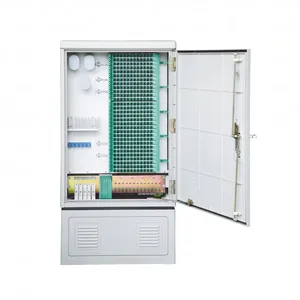
JFDC-288A Fiber Distribution Cabinet
288-port outdoor FDC with continuous-radius splice trays and dedicated cable storage compartments.
View Product →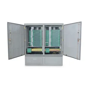
JFDC-1152A Fiber Distribution Cabinet
1152-port high-capacity FDC with 24-module frame and bend-radius-limited cable entry pathways.
View Product →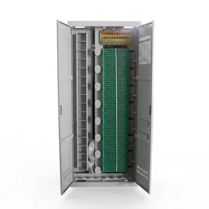
JODF-C2 Optical Distribution Frame
1440-port rack-mount ODF with integrated cable management fingers and bend radius limiting guides.
View Product →Related Articles
Fiber Distribution Cabinet Buying Guide
Capacity planning, material selection, and IP rating for FDC procurement decisions.
Read Article →
Fiber Termination: Process & Best Practices
Step-by-step fiber termination guide covering fusion splicing, preparation, testing, and field best practices.
Read Article →
How to Install Splice Tray in FDC
Step-by-step splice tray installation guide with fiber routing and bend radius best practices.
Read Article →References
Key takeaway
Bend radius violations do not happen because installers are careless — they happen because the enclosure does not make proper fiber routing the path of least resistance. The fiber distribution cabinet and patch panel are not passive containers; they are the structural system that either enforces or undermines your bend radius compliance. Choose enclosures with continuous-radius tray channels, dedicated slack storage, and labeled routing paths. Pair them with G.657 fiber for the bends you cannot avoid. And verify with OTDR baseline comparison after 3-6 months — that is when the hidden bend violations reveal themselves.
Related products