Pole Mount Cabinet Installation Guide: Step-by-Step Field Instructions
By Jergeo Engineering Team | Updated August 2026 · 11 min read
A pole mount cabinet is a fiber distribution cabinet designed for installation on utility poles — concrete, steel, or wood — using band clamps, bracket arms, or through-bolt hardware. Unlike pad-mounted or wall-mounted cabinets, pole mount installations lift the cabinet off the ground to protect against flooding, vandalism, and accidental vehicle impact. They are the standard choice for aerial FTTH deployments, rural broadband networks, roadside fiber access points, and any scenario where ground-level mounting is impractical or unsafe.
This guide covers the complete installation process for pole mount fiber distribution cabinets, from pre-installation site assessment through final inspection. The procedures apply to Jergeo's JFDC-72A, JFDC-144A, and JFDC-288A fiber distribution cabinets when configured with pole mounting accessories.
Summary
Pole mount cabinet installation requires assessing pole condition and load capacity, selecting the right mounting hardware (band clamps, bracket arms, or through-bolts), lifting and positioning the cabinet at the correct height, securing all cable entries, and grounding for lightning protection. Proper installation ensures IP65 or IP68 weatherproofing, structural stability under wind load, and 25+ year service life.

Pre-installation: Site Assessment and Pole Checks
Before any hardware goes up the pole, you need to verify three things: the pole can carry the load, the diameter matches your mounting hardware, and there is enough clearance around the installation point.
Pole condition
Inspect the pole for structural damage. Concrete poles should have no exposed rebar, deep spalling, or horizontal cracks above the mounting zone. Steel poles must be free of rust-through, dents, or deformation at the clamp contact area. Wood poles — still common in North American rural deployments — must not show rot, insect damage, or lean exceeding 5° from vertical. A compromised pole will fail under wind load long before the cabinet does.
Check the pole's load rating plate or documentation. The pole must support the cabinet weight (typically 25–60 kg empty, up to 120 kg with cable and hardware) plus a wind load safety factor of at least 1.5× the projected cabinet area. If the pole is shared with power lines or other telecom equipment, obtain written authorization from the pole owner before proceeding.
Pole diameter measurement
Measure the pole's outer diameter at the exact mounting height using a caliper or flexible tape measure. Standard band clamps fit poles from 150mm to 300mm diameter. For poles outside this range, you need either a custom-length band or a dedicated bracket system. Record the measurement — clamp selection depends on it.
For tapered concrete poles, measure at the mounting point itself, not at the base. A pole that is 250mm at ground level may only be 200mm at 4 meters height.
Clearance requirements
Verify minimum clearances: at least 600mm behind the pole for cable loop storage and entry access, 300mm on each side of the cabinet for door opening, and the required vertical ground clearance (typically 3.0–4.5m depending on local code). If the pole carries power lines, maintain the utility company's minimum separation distance — usually 1.0m between the highest telecom hardware and the lowest power conductor.
Mounting Hardware Options
Three mounting methods are standard for pole mount fiber distribution cabinets. The choice depends on pole type, cabinet weight, and whether the pole allows through-bolting.
Band clamp mounting
Stainless steel band clamps wrap around the pole circumference and bolt to threaded brackets on the cabinet rear panel. This is the most common method for concrete and steel poles where drilling is not permitted. Standard bands are 20mm wide × 1.5mm thick 304 stainless steel, rated for 500 kg tensile strength. Use two bands (top and bottom) for cabinets up to 288 ports. For larger 576-port cabinets, use three bands or a dedicated pole yoke bracket.
Band clamps distribute load evenly around the pole and do not require penetration. However, they rely entirely on friction — improper torque or incorrect band sizing is the most common cause of cabinet slippage on poles.
Bracket with through-bolts
Steel bracket arms bolt through the pole (for wood poles) or into pre-drilled holes (for steel poles with permission). The cabinet mounts to the bracket arms via M10 or M12 bolts. This method provides the highest mechanical security but requires the pole owner's permission to drill. Always seal drilled holes with marine-grade epoxy or silicone to prevent moisture ingress into wood poles.
Pole-top or crossarm mounting
Some installations mount the cabinet below the pole top plate or on an existing crossarm (the horizontal arm that carries distribution cables). Crossarm mounting uses U-bolts that clamp to the crossarm timber. This positions the cabinet at maximum height for aerial cable alignment but requires the crossarm to support the additional load. Verify crossarm structural integrity before using this method.
Step-by-Step Installation Procedure
Step 1: Mark the mounting position
Using the cabinet's mounting hole template (supplied with pole mount accessory kit) or measured dimensions, mark the exact positions for band clamp slots or bracket bolt holes on the pole. The cabinet should be centered on the pole face, with the door oriented toward the cable approach direction — typically the road or sidewalk side for maintenance access. Mark horizontal level lines to ensure the cabinet will sit plumb.
Step 2: Assemble the mounting bracket
Pre-assemble the band clamps or bracket arms on the ground. Thread the stainless steel bands through the buckle slots and loosely attach them to the cabinet's rear mounting rails. Do not tighten at this stage — you need the bands to slide freely during positioning. If using bracket arms, bolt them to the cabinet rear panel using the supplied M10 hardware, torquing to 25 N·m.
Step 3: Lift and position the cabinet
Use a pole climber, bucket truck, or portable gin pole to lift the cabinet to the marked height. For cabinets under 40 kg, two technicians with a rope and pulley system can manage the lift. For heavier units, mechanical lifting is mandatory. Position the cabinet against the pole, aligning it with the marked level lines. The cabinet must be perfectly vertical — use a spirit level on the door edge to check plumb in both axes.
Step 4: Tighten all mounting hardware
Once positioned, tighten the band clamps or bracket bolts. For band clamps, torque each band to the manufacturer's specification (typically 40–50 N·m on the buckle bolt). Tighten in alternating pattern — top band first, then bottom, then re-check top — to draw the cabinet evenly against the pole surface. Verify the cabinet has not shifted during tightening.
For through-bolt installations, install flat washers and spring washers on both sides, then torque to 35 N·m for M10 bolts in wood. Apply a dab of silicone sealant over each bolt head after final tightening.
Step 5: Route cables through entry points
Open the cabinet door and remove the blank entry port plugs. Route feeder cables through the bottom entry ports (most pole mount cabinets use bottom-entry to allow drip loops before cable enters the cabinet). Pull cables through the gland or seal ring, leaving enough slack inside for fiber management. Install cable clamps inside the cabinet to anchor the cable strength member to the cabinet's internal grounding bar.
Step 6: Seal and close
Install cable glands on all active entry ports, tightening the compression nut until the seal ring compresses around the cable jacket. Plug all unused ports with blank plugs and compression seals. Close the cabinet door, engage the latch, and install the padlock. Verify the door gasket is fully seated — run a finger around the entire perimeter to confirm even compression.
Common Installation Problems and Fixes
Cabinet slides on the pole after installation
Caused by insufficient band clamp torque or wrong band size for the pole diameter. Solution: remove the cabinet, select the correct band width and length, clean the pole surface of debris and ice before re-installation, and torque to specification. For smooth concrete poles, add a rubber friction pad between the band and pole surface.
Water ingress through cable entry ports
The gland compression nut was not fully tightened, or the seal ring diameter does not match the cable outer diameter. Each gland seal is sized for a specific cable OD range (e.g., Φ7–12mm or Φ12–20mm). Using a Φ7–12mm gland on a 15mm cable will never seal properly. Replace the gland with the correct size range.
Cabinet door does not close flush after mounting
The cabinet frame twisted during pole clamping — the bands pulled one side tighter than the other. Loosen all bands, reposition with a spirit level, and tighten in the star pattern (top-left, bottom-right, top-right, bottom-left) to distribute force evenly.
Band clamps corrode prematurely
Using standard steel bands instead of stainless steel in a coastal or high-humidity environment. Always specify 304 or 316 stainless steel bands for pole mount installations. Replace corroded bands immediately — a corroded band can fail under wind load without warning.
Material Considerations for Pole Mounting
The cabinet material matters more for pole mount than for ground-level installations, because the pole mount environment exposes the cabinet to higher wind loads, wider temperature swings, and more UV radiation at elevation.
SMC (Sheet Molding Compound) is the preferred material for most pole mount applications. It weighs 30–40% less than equivalent steel cabinets, reducing the load on the pole and mounting hardware. SMC is non-corrosive, UV-stable, and maintains structural integrity from −40°C to +130°C. For aerial deployments where every kilogram of pole load matters, SMC is the clear choice.
Stainless steel (304 or 316) provides the highest impact resistance and is appropriate for high-vandalism areas or locations where the cabinet may be struck by vehicles, ice, or falling branches. The weight penalty (45–70 kg for a 288-port cabinet) requires a pole rated for the additional load and wider band clamps to distribute the force.
ABS plastic is suitable for sheltered pole installations — under bridge overpasses, inside equipment enclosures, or in covered pole-top platforms. ABS degrades under prolonged UV exposure and should not be used in direct sunlight without a UV-rated paint coating.
Wind, Water, and Lightning Protection
Wind load
A pole mount cabinet acts as a wind sail. The projected area of a typical 288-port cabinet is approximately 0.35 m². At a wind speed of 120 km/h (common design specification for coastal areas), this generates roughly 500 N of lateral force on the mounting hardware. Ensure all band clamps and brackets are rated for at least 2× the calculated wind force. In typhoon or hurricane zones, add supplemental guy wires or a wind deflector plate above the cabinet.
Water protection
Install a drip loop on all incoming cables — the cable should droop below the entry point before entering the cabinet gland. This prevents water from running down the cable jacket directly into the seal. Orient cable entry ports downward whenever possible. For bottom-entry cabinets, add a cable drip tray below the entry points to catch condensation and rain splash.
Lightning protection
Connect the cabinet's internal grounding busbar to a grounding rod using a minimum 6mm² bare copper conductor. The grounding rod should be driven at least 2.4m into earth with a ground resistance of less than 10 ohms. Install surge protection devices (SPDs) on any metallic cable strength members entering the cabinet. For poles in high keraunic density zones (more than 40 thunderstorm days per year), install a lightning mast or rod extending at least 300mm above the cabinet roof.
Post-Installation Inspection Checklist
- ✅ Cabinet is plumb and level — verified with spirit level on door edge
- ✅ All band clamps or bracket bolts torqued to specification
- ✅ Cabinet door opens and closes freely, gasket fully seated
- ✅ All cable entry glands tightened, unused ports plugged
- ✅ Drip loops installed on all incoming cables
- ✅ Grounding conductor connected and ground resistance measured (≤10 ohms)
- ✅ Surge protection devices installed on metallic cable members
- ✅ Cable strength members anchored to internal grounding bar
- ✅ Padlock installed and key recorded in maintenance log
- ✅ Cabinet labeled with asset ID, installation date, and fiber count
- ✅ Installation photos documented for maintenance records
- ✅ Work area cleared — no hardware scraps, zip tie tails, or tools left behind
Related Products
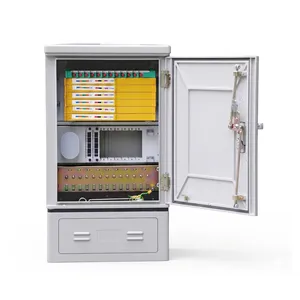
JFDC-72A Fiber Distribution Cabinet
72-port outdoor cabinet — compact design ideal for pole mount in aerial FTTH access networks
View Product →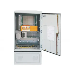
JFDC-144A Fiber Distribution Cabinet
144-port outdoor cabinet for distribution layer networks, supports pole mount with band clamp kit
View Product →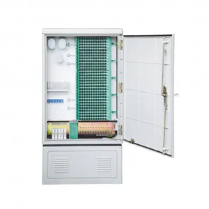
JFDC-288A Fiber Distribution Cabinet
288-port outdoor cabinet with SMC or stainless steel options, pole mount bracket compatible
View Product →Related Articles
Fiber Distribution Cabinet Buying Guide
Capacity planning, material selection, and IP rating explained for FDC procurement.
Read Article →
Fiber Cabinet Materials: SMC vs Steel vs ABS
Weight, IP rating, UV resistance, and cost comparison for outdoor cabinet materials.
Read Article →
Outdoor Fiber Termination Box Guide
Capacity, IP rating, and wall-mount vs pole-mount options for fiber termination boxes.
Read Article →References
- FOA Reference Guide to OSP Installation — The Fiber Optic Association's reference on outside plant installation practices, including pole mounting and cable entry procedures
- IEC 60794 — International standard for optical fibre cables covering mechanical and environmental requirements for outdoor installations
- IEC 60794 — Optical fiber cable standards covering installation requirements, mechanical loading, and environmental testing for outdoor plant cables
Key takeaway
Pole mount cabinet installation succeeds or fails at the details. Measure the pole diameter before ordering clamps. Torque every band to specification in the correct sequence. Install drip loops on every cable — water follows cable jackets downhill into the cabinet if you skip this step. Ground everything — an ungrounded pole mount cabinet is a lightning rod sitting 4 meters above ground. The hardware is rated for 25 years, but only if the mounting, sealing, and grounding are done right on day one.
Related products