How to Install Splice Trays in a Fiber Distribution Cabinet
By Jergeo Engineering Team | Updated July 2026 · 9 min read

Installing splice trays inside a fiber distribution cabinet (FDC) looks straightforward on paper — slide the tray in, snap it down, done. In practice, it is the step where most future signal loss gets baked in. A tray that is mounted at a slight angle, where fibers cross at the splice holder transition, or where the slack coil sits a millimeter below minimum bend radius, will produce intermittent macrobend loss that shows up six months later during a hot summer or after the cabinet door gets slammed shut. The procedure below goes from the tray you pull out of the box to the final OTDR sweep, with specific references to Jergeo JFDC-series cabinets and JST-series splice trays.
Summary
Proper splice tray installation in an FDC requires: correct tray orientation in the holder bracket, 1 m minimum fiber slack per side, ≥30 mm bend radius throughout the routing path, color-order fiber arrangement from blue to aqua, and hand-tight cable ties at strain relief points. Skipping any of these steps creates a future service call.
The procedure below assumes you are working with a Jergeo JFDC-series outdoor fiber distribution cabinet using standard 12-fiber or 24-fiber JST-A series splice trays. The same principles apply to most rack-mount ODFs and wall-mount enclosures — only the mounting hardware changes. We wrote this from the factory floor, not the marketing deck: every number here comes from either Corning standard recommended procedures, CommScope installation manuals, or TIA-568.3-D.
Tools and materials you need
Do not open the cabinet until you have everything laid out. In a pole-mounted or underground vault installation, climbing back down for a missing cable tie adds 20 minutes per trip. Here is everything you need for a splice tray installation inside an FDC:
Hand tools
- Fiber stripper — two-stage (jacket + buffer), with a 250 μm coating stripper for bare fiber prep
- Cable cutters — for trimming buffer tube and strength members inside the cabinet
- Aramid yarn scissors — regular scissors will dull instantly on Kevlar
- Crimp tool (e.g., Corning M67-020 or equivalent) for buffer tube crimp tabs on the tray
- Torque screwdriver with 0.4–0.6 Nm range, for any screw-mounted tray brackets
- Cable tie tensioning tool — or just use hand-tight and a flush cutter; do not over-tighten
- Flush-cut diagonal cutters — for trimming cable ties flush to avoid sharp edges
Splicing equipment
- Fusion splicer with the correct program loaded for the fiber type (G.652D, G.657A2, etc.)
- Precision cleaver — ≤0.5° cleave angle, calibrated within the last 6 months
- Heat oven — built into most modern splicers, for heat-shrink splice sleeves
- Optical power meter / VFL — for continuity and loss verification after each tray
Consumables
- Splice protection sleeves — 40 mm or 60 mm heat-shrink type with stainless steel reinforcement rod; use one size per tray, never mix
- Isopropyl alcohol — ≥99% purity, in a squeeze bottle or pre-saturated wipes
- Lint-free wipes — non-woven polyester, never paper towels or regular cloth
- Cable ties — 2.5 × 100 mm nylon, black for UV resistance in outdoor cabinets
- Labeling materials — heat-shrink labels or weatherproof printable tags; paper labels fall off
- Safety glasses — ANSI Z87 rated; bare fiber ends are like tiny glass needles
Pro tip: If you are working in a dusty or outdoor environment, set up a small portable work table with a clean work mat next to the cabinet. Never splice on the ground or on a dirty surface — contamination from a single grain of sand inside the splice sleeve will cause a loss spike months later.
Before you start: cabinet prep and tray inspection
Most bad splice tray installations go wrong before the first fiber is stripped. Take two minutes to verify the cabinet and the tray are ready.
Open the FDC door and check that the tray holder brackets are securely fastened to the cabinet chassis. On Jergeo JFDC-series cabinets, the brackets come pre-installed from the factory, but they can shift during shipping if the cabinet took a hard knock. Gently wiggle each bracket with one hand — it should not move. If a bracket is loose, tighten the four mounting screws on the backplate to 0.5 Nm before proceeding.
Next, inspect each splice tray before you take it out of the plastic bag. Check for:
- Cracks or deformation in the tray body (shipping damage is common with thin ABS trays)
- Splice holders are firmly seated and the adhesive backing has not peeled
- The hinge pin on the back of the tray is straight and undamaged
- The tray cover clips into place cleanly on all four corners
Reject any tray that fails these checks. A cracked tray will not hold fiber properly, and you will not discover it until you are halfway through the splice job.
Step-by-step installation procedure
Step 1: Mount the tray in the holder bracket
Hold the splice tray vertically over the tray holder bracket, with the hinge side facing the rear of the cabinet. Insert the tray hinge pin into the designated slot on the bracket. You should feel it seat with a definite click.
Lift the red tray support latch upward with your thumb, then slowly lower the front of the tray until it rests on the latch. The tray should tilt forward at approximately a 30-degree angle when fully seated — this is the working position that gives you access to the interior. If the tray sits flat or falls through, you did not engage the support latch correctly — pull it out and try again.
This procedure is standard across CommScope, Corning, and Jergeo cabinets. The exact latch shape varies by manufacturer, but the principle is the same: hinge in back, support latch in front, tray tilts for work and folds flat for storage.
Step 2: Route the buffer tube into the tray
Bring the buffer tube (or tight-buffered fiber, or ribbon transport tubing) from the cable entry side of the cabinet up to the tray corner. On Jergeo JST-A trays, fibers enter and exit at the same corner — this keeps routing consistent across the entire stack.
Strip the buffer tube to expose 182 cm (72 in) of bare fiber. This length gives you two full loops around the inside perimeter of the tray, per Corning's standard procedure for OSE-series trays. If you are working with a 24-fiber high-density tray, you may need more; start with 2 meters and trim from there if the slack is excessive — never start short and wish you had more.
Secure the buffer tube at the tray entry point using one of these methods, depending on tray type:
- Crimp-tab trays: Use the inner crimp tab first. Position the buffer tube approximately 1 cm (3/8 in) beyond the tab, then crimp with a crimp tool adjusted to the tube's outer diameter. Do not crush the tube — the crimp should hold the tube without deforming it.
- Cable-tie trays: Thread a cable tie through the holes in the tray lip. Position the buckle to one side of the cable bundle (not on top), so it does not interfere with the tray cover. For multiple pigtails, wrap 1.5 inches of vinyl tape around the bundle first to protect the jackets. Hand-tighten only.
- Ribbon trays: Use a ribbon retention grommet or split grommet. Stand the ribbons on edge (vertical plane), not flat. Never twist the ribbon bundle as it enters the tray.
Step 3: Plan fiber routing and splice order
Before you strip a single fiber, decide the routing layout. The standard pattern has Cable A entering from the left side, Cable B entering from the right side, and splices sitting in the holders along the bottom or center. Most tray covers have a printed routing diagram on the inside — follow it.
Fibers must be routed in color order following the standard 12-color sequence: blue (1), orange (2), green (3), brown (4), slate (5), white (6), red (7), black (8), yellow (9), violet (10), rose (11), aqua (12). Both cables route their position-1 fiber to the same splice holder, so color-to-color splicing is automatic. This is not a style choice — it is the only way a future technician can predict which fiber is in which slot without tracing every one.
Common mistake: It is tempting to route the blue fiber to the closest holder to save a few centimeters of length. Do not do it. Out-of-order routing destroys the predictability of the entire tray. Work in order, even if it means the first few fibers have slightly more slack.
Step 4: Splice and seat each fiber
Work one fiber at a time, from position 1 to position 12 (or 24). For each pair:
- Slide a heat-shrink protection sleeve onto one fiber before you splice. This is the most common rookie mistake — splice first, realize you forgot the sleeve, have to cut and re-do.
- Strip, clean, and cleave both fiber ends. Cleave angle must be ≤0.5° for reliable low-loss splices.
- Run the fusion splice. Target loss is ≤0.05 dB per splice; re-do any splice over 0.1 dB.
- Slide the protection sleeve over the splice point, center it, and heat in the oven according to the sleeve manufacturer's spec (typically 30–60 seconds at 150–180 °C).
- Seat the protected splice into the correct holder slot. It should click into place — if it sits loose, the sleeve may not have shrunk fully or you have the wrong sleeve size for the holder.
After every four splices, pause and check that the fibers entering and exiting the splice holders do not form a tight bend right at the holder edge. This transition point is where macrobend loss most often occurs — the fiber goes straight into the holder then immediately curves to follow the loop guide. If the bend looks sharp, pull a few millimeters of slack from the coil to relax it.
Step 5: Coil the slack
With all splices seated, coil the remaining slack around the tray's loop guide. The coils should sit flat in the guide channel, follow the radius of the guide, and not cross other fibers. If the slack is too long for one loop, take a second loop — both loops go in the same channel, one inside the other.
Minimum bend radius: 30 mm. For G.652 standard single-mode fiber, this is the loaded minimum per IEC 60793-2-50. The tray's internal guides are designed to enforce this radius, which means if you are cramming extra fiber into the tray and the coils are not sitting in the guide, you are violating it. Do not force it.
Never trim slack to make it fit. The slack is there for a reason — future re-splicing, re-routing, or troubleshooting. TIA-568.3-D recommends at least 1 meter of stored slack per fiber at each splice point, which gives you enough length for at least two re-splice attempts. If you cut the slack short, the next technician will have to pull more cable from the cable entry — which means re-doing the strain relief, the seal, and possibly the entire cable prep.
For ribbon fiber, the minimum coiling diameter is 60 mm to keep all fibers in the ribbon within bend radius simultaneously. 12-fiber ribbons need twice the bend radius of single fibers because the fiber on the outside of the bend traces a tighter radius than the fiber on the inside.
Step 6: Close, label, and secure the tray
Before you put the cover on, document the tray. Write or attach a label that includes:
- Cable IDs for both sides (feeder cable and distribution cable), matching as-built drawings
- Splice count and date
- Technician initials
- Tray number in the stack (e.g., "Tray 3 of 12")
ANSI/TIA-606-C administration standards require splice points to be recorded in the network documentation system with OTDR loss values archived at installation. This is the baseline you compare against when troubleshooting a future fault.
Clip the tray cover on, making sure all four corners seat properly. If the cover does not close flat, do not force it — something is sticking up. Common culprits: a splice sleeve that is not seated all the way, a fiber loop that has popped out of the guide channel, or a cable tie buckle in the wrong place. Forcing the cover shut will crush a fiber.
Once closed, fold the tray up to its stowed position by lifting the front and lowering the support latch. The tray should sit flat against the bracket. If you have multiple trays in a stack, install them from the back forward or from bottom to top, depending on the bracket design. When all trays in a bracket are installed, wrap the hook-and-loop strap around the entire stack and cinch it gently — this prevents trays from swinging open if the cabinet door is slammed. Do not over-tighten the strap; it is a retainer, not a clamp.
Post-installation verification
Do not close the cabinet door yet. Verify every tray before you walk away:
- Visual inspection — use a flashlight and check that no fiber is pinched, no splice is sitting askew in its holder, and no slack has popped out of the guide channels
- OTDR or power meter test — test each fiber end-to-end. Any unexpected loss event above 0.1 dB at a splice point means you need to open that tray and investigate
- Tray security check — gently tug each tray forward to confirm it is engaged in the bracket and cannot fall out
- Label verification — every tray must be labeled on both the front edge (visible when stowed) and the inside (visible when opened)
- Door clearance check — close the cabinet door slowly. If it hits any tray or fiber, the stack is not seated correctly. Fix it before you leave.
Common mistakes and how to avoid them
Crossing fibers in the tray
Fiber over fiber creates pressure points and makes future access impossible — you cannot reach fiber 5 without disturbing fiber 8. Always route fibers in parallel, in color order, with no crossing. If you have more fibers than one side of the tray can handle cleanly, you need more trays, not tighter packing.
Tight bends at the splice holder transition
Where the bare fiber emerges from the splice holder and curves into the slack coil, the bend can sneak below minimum radius because the fiber is free at that point. Watch this transition on every fiber. If a bend looks tight, it is tight. Pull 5–10 mm of slack from the coil to relax it.
Not leaving enough slack
Cutting slack short to make the tray look neat is the single most expensive long-term mistake you can make. The next re-splice will require pulling cable from the entry point — redoing strain relief, re-sealing the cable gland, and possibly disturbing adjacent cables. Always leave at least 1 m per fiber side. Coil the rest; it does not hurt anything.
Mixing sleeve sizes in the same tray
If you use 40 mm sleeves for some splices and 60 mm for others, some splices will sit higher than others in the holders. The tray cover will press on the taller ones, creating microbend loss. Use one sleeve size per tray. If you need different sizes, use separate trays.
Over-tightening cable ties
A cable tie that is too tight crimps the buffer tube and creates a loss point. Cable ties should be hand-tight — snug enough to hold the cable in place, but you should still be able to rotate the tube with your fingers. Use a tensioning tool if you are inconsistent by hand, and always cut the tail flush.
Skipping the bend radius check on the way out
When you fold a tray back into its stowed position, the slack coil shifts. A fiber that was fine at 30 mm when the tray was open might be pinched to 20 mm when the tray is flat against the bracket. Always do a final visual check after closing each tray, not just when it is tilted open.
Related Products
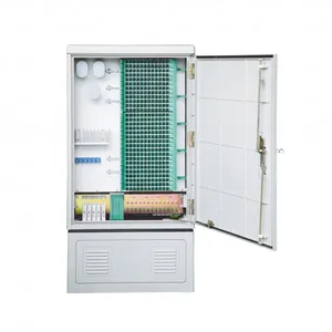
JFDC-288A Fiber Distribution Cabinet
Outdoor SMC and steel cabinets for FTTx deployments, 72–1152 port capacity
View Product →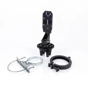
JFSC-L144A Fiber Optic Splice Closure
Dome and horizontal closures for OSP splicing, IP68 rated, 48–288 fibers
View Product →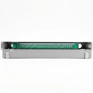
JODF-U1 Fiber Optic Patch Panel
Rack-mount and wall-mount patch panels, LC/MPO, 12–144 ports
View Product →References
- Corning OSE Splice Trays SRP 001-285 — standard recommended procedure for OSE-series splice tray installation and fiber routing
- CommScope ODF-SPLCAB-24 User Manual — splice tray installation procedure for universal mount splice cabinets (TC-96282-IP, Rev C, May 2020)
- Sumitomo SRP SP-F05-035 — single-fiber splice tray installation recommended procedure
- TIA-568.3-D — fiber optic components and cabling standard, including bend radius and service loop requirements
Key takeaway
Splice tray installation is 80% discipline and 20% technique. The tools are simple; the hard part is doing it the same way every time — color order, minimum bend radius, 1 m slack, proper labeling. A tray installed with these rules will still be clean and predictable 15 years from now when the next technician opens it. One installed without them will be a troubleshooting nightmare by year two. Jergeo JST-series trays and JFDC-series cabinets are designed to make the correct procedure the easy one — use them the way they are intended.
Related products
Related Articles

Fiber Splice Closure Guide
Dome vs inline splice closure selection — closures use the same tray principles.
Read Article →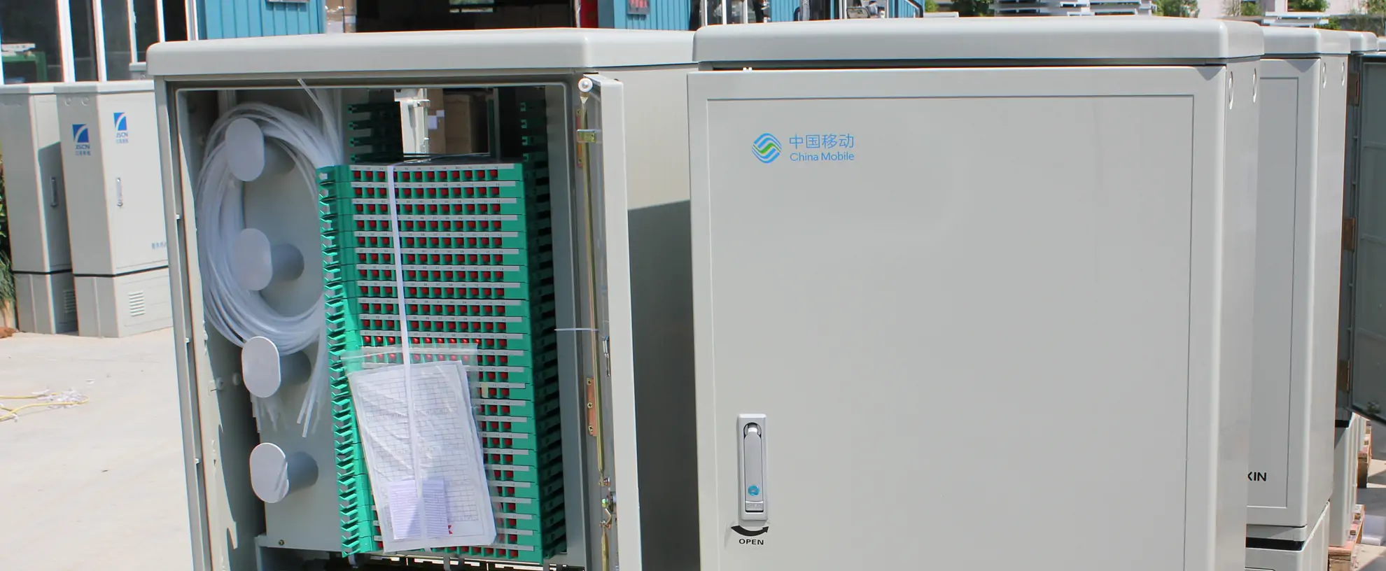
FDC vs FDH vs ODC: What's the Difference?
Understand the three cabinet naming conventions and which one applies to your project.
Read Article →
Fiber Distribution Cabinet Buying Guide
How to spec FDCs with tray-friendly internal structures for easy field installation.
Read Article →