Fiber Termination: Process & Best Practices
By Jergeo Engineering Team | Updated August 2026 · 12 min read
Fiber termination is the process of preparing, joining, and protecting the end of an optical fiber so it can connect to network equipment — a patch panel, a distribution cabinet, a splitter, or another cable. It sounds straightforward. It's not. A single bad termination can add 0.5 dB of loss to a link that was budgeted for 0.1 dB per splice. Multiply that across 48 fibers and you've blown your entire power budget before the network even goes live.
We've terminated fiber in data centers, on telephone poles at -15°C, and inside cramped manholes with standing water. The process is the same everywhere. The mistakes are also the same everywhere. This guide covers what works, what doesn't, and why — based on actual field experience, not a manufacturer's brochure.
Summary
Fiber termination involves stripping cable jackets, preparing bare fibers, joining them via fusion splicing or mechanical connectors, protecting splice points in trays, and verifying performance with OTDR testing. The two methods serve different use cases: fusion splicing for permanent links with ≤0.1 dB loss, mechanical connectors for field-deployable patch cords with ≤0.5 dB loss. Best practices focus on cleave quality, contamination control, and bend radius management — these three factors account for most field failures.

Why Fiber Termination Matters
Every connection point in your fiber network is a potential failure point. A poorly terminated fiber doesn't just add loss — it creates a weak spot that degrades over time. Temperature cycling, vibration, and moisture intrusion turn a marginal splice into a complete link failure six months after installation.
We've seen this pattern dozens of times. A network passes OTDR testing at commissioning, but starts throwing errors after the first winter. The root cause? A bad cleave angle during termination that created a micro-crack in the fiber. It worked fine at 20°C in the lab. At -10°C in the field, the crack propagated. The link died.
That's why termination quality isn't just about passing today's test. It's about surviving tomorrow's environment. The Fiber Optic Association (FOA) reports that improper termination accounts for over 60% of field fiber network failures. Not the cable. Not the equipment. The termination.
Termination Methods: Fusion Splicing vs. Mechanical Connectors
There are two ways to terminate fiber. Fusion splicing melts two fibers together with an electric arc. Mechanical termination aligns fibers inside a precision connector using index-matching gel. Both work. Both have their place. But they are not interchangeable.
Fusion Splicing
Fusion splicing is the gold standard for permanent fiber termination. A fusion splicer aligns two stripped, cleaved fibers with micron precision, then discharges an electric arc (typically 2,000°C) to melt the glass ends together. The result is a continuous glass joint with insertion loss as low as 0.02 dB for singlemode fiber. That's essentially invisible to the optical link budget.
Modern core-alignment splicers (Fujikura, Sumitomo, INNO) use multi-camera systems to align the fiber cores — not just the cladding — which matters for singlemode fiber where the 9μm core sits inside a 125μm cladding. If your splicer only does cladding alignment, expect 0.05–0.1 dB loss per splice instead of 0.02 dB. For long-haul links with hundreds of splices, that difference adds up fast.
Best for: Outside plant splicing, cable-to-cable joints, permanent connections inside fiber distribution cabinets and splice closures. Any application where you want the lowest possible loss and you won't need to disconnect the fiber later.
Mechanical Termination (Field-Installable Connectors)
Mechanical connectors skip the fusion splicer entirely. You strip the fiber, cleave it, insert it into a pre-polished connector body that contains a factory-polished ferrule and index-matching gel, and crimp. The fiber end butts against the factory-polished surface inside the connector. No arc, no electricity needed. You can terminate a connector in a closet with no power outlet.
Typical insertion loss is 0.2–0.75 dB per connector — higher than fusion, but within TIA-568 limits for most applications. The trade-off: mechanical connectors are faster in the field (no splicer warm-up, no electrode maintenance), but each connector costs more per unit than a splice. At scale — say, terminating 576 fibers in a distribution cabinet — fusion splicing is both cheaper and lower-loss.
Best for: Patch cord assembly, emergency restoration, temporary links, FTTH drop cable terminations at the ONT side, and any situation where a fusion splicer is impractical.
Fusion Splicing vs. Mechanical Termination — Quick Comparison
| Factor | Fusion Splicing | Mechanical Termination |
|---|---|---|
| Insertion loss | 0.02–0.1 dB | 0.2–0.75 dB |
| Return loss | ≥60 dB | ≥35 dB (UPC), ≥55 dB (APC) |
| Time per fiber | 60–90 seconds | 90–120 seconds |
| Equipment cost | $3,000–$15,000 splicer | $50–$200 tool kit |
| Cost per termination | $0.50–$2 (sleeve + labor) | $3–$8 per connector |
| Reversibility | Permanent | Connector can be replaced |
| Power required | Yes (electric arc) | No |
Fiber Termination: Step-by-Step Process
The termination process is the same whether you're splicing inside a fiber distribution cabinet, loading a patch panel, or terminating at an outdoor box. Preparation takes 60% of your time. The actual splice or connector install is the quick part.
Step 1: Cable Preparation and Jacket Stripping
Start by measuring how much cable jacket to remove. For most splice closures and distribution cabinets, strip 1.0–1.5 meters of outer jacket to give you working length for fiber routing and slack storage. Use a cable jacket slitter — not a utility knife. A utility knife cuts too deep and scores the buffer tubes underneath. We've seen technicians nick buffer tubes so badly they had to cut back and re-strip, wasting 30 cm of cable they couldn't afford to lose.
After removing the jacket, expose the strength member (aramid yarn or fiberglass rod). Anchor it immediately to the cable clamp or grounding bar inside the enclosure. The strength member carries all the tensile load — if it's not anchored, every gram of pull force transfers to your fragile glass fibers.
Cut the water-blocking tape or gel-filled bundle to expose the buffer tubes. Clean water-blocking gel off the tubes with a lint-free wipe and isopropyl alcohol. Gel is hydrophobic — it repels the alcohol — so you may need two passes. Skipping this step means gel transfers to your fiber stripper and contaminates every fiber you strip afterward.
Step 2: Fiber Stripping
Strip 30–40mm of the 250μm coating (or 2mm of the 900μm tight buffer) from each fiber using a precision fiber stripper. The stripper must match the fiber's coating diameter — a 250μm stripper won't work correctly on a 900μm buffer and vice versa. Using the wrong stripper creates micro-bends or cracks in the bare glass that don't show up until weeks later.
Strip in one smooth motion. Don't squeeze harder if the coating doesn't come off — reposition the stripper and try again at the correct pressure. Any nick or scratch on the 125μm glass surface becomes a fracture point. The fiber will break during cleaving, or worse, survive cleaving and fail in service.
After stripping, wipe the bare fiber once with a lint-free wipe dampened (not dripping) with 99% isopropyl alcohol. Wipe in one direction — don't rub back and forth. Rubbing pushes contamination into the glass surface.
Step 3: Cleaving
This is where most termination problems start. The cleave must produce a perfectly flat, perpendicular end face on the bare fiber. A good cleave angle is ≤0.5° for fusion splicing, ≤1.0° for mechanical connectors. A bad cleave looks fine to the naked eye. It shows up as high splice loss on the OTDR trace.
Use a precision cleaver with a diamond or tungsten carbide blade. Set the fiber protrusion length according to the cleaver's spec sheet — typically 5–16mm for a precision cleaver. Score the fiber with the blade, then apply controlled tension to snap it. The fracture propagates along the score line and produces the end face.
From our field experience, a worn cleaver blade is the single most common cause of high-loss splices. Most cleaver blades are good for 30,000–50,000 cuts. If your splice loss suddenly creeps up from 0.03 dB to 0.08 dB across the board, the blade is the first thing to check — not the splicer.
Step 4: Fusion Splicing or Connector Assembly
For fusion splicing: Open the splicer's fiber clamps. Place the cleaved fiber into the V-groove, with the cleaved end protruding past the electrode gap. Close the clamp. Repeat on the opposite side. The splicer's cameras will display the fiber end faces on screen — verify both ends look clean and perpendicular before starting the arc.
Press "Arc" or "Auto." The splicer runs a pre-arc (cleaning discharge), aligns the cores using its imaging system, then fires the main arc to fuse the fibers. The whole cycle takes 8–15 seconds on modern splicers. The splicer estimates splice loss based on the post-splice image analysis — trust this estimate as a rough guide, but confirm with OTDR.
After the splice completes, open the clamps and carefully lift the fiber. Slide a heat-shrink splice protector over the splice point (if using a sleeve-type protector), then place it in the splicer's heater for 30–60 seconds. The protector reinforces the splice mechanically — bare fused fiber is as fragile as it was before splicing.
For mechanical connectors: Insert the cleaved fiber into the connector body until it contacts the internal alignment sleeve. You should feel a soft stop. Some connectors have a visual indicator (color change window) that confirms the fiber has reached the back of the ferrule. Crimp the connector's strain relief boot, then test the end face with a fiber inspection scope.
Step 5: Slack Storage and Fiber Routing
This step separates a professional termination from a mess. Every terminated fiber needs slack — typically 1–2 meters of excess fiber coiled neatly in the splice tray or storage compartment. The slack lets you re-terminate if a connector fails, or re-splice if a fiber breaks during future maintenance.
Route fibers in the standard TIA-598 color sequence: blue, orange, green, brown, slate, white, red, black, yellow, violet, rose, aqua. Consistent color order means the next technician who opens the cabinet can trace fibers without guessing. We've opened cabinets where fibers were stuffed in randomly — it adds 30 minutes to every troubleshooting visit.
Respect the minimum bend radius. For singlemode fiber, that's 30mm under no load (long-term), 15mm during installation (short-term). For 900μm buffered fiber, use 40mm long-term. Tighter bends cause macrobend loss — light leaks out of the core at the bend. At 1310nm, the loss is moderate. At 1550nm, a tight bend can cause 1–2 dB of additional loss that you won't understand unless you know to look for it.
Use splice trays with the correct capacity. Don't force 24 splices into a 12-splice tray — the excess fiber will press against the tray walls and create microbend loss. If you need more capacity, use a larger tray or add more trays inside the fiber termination enclosure.
Step 6: Testing and Verification
Never close a cabinet without testing. At minimum, run an OTDR trace from both ends of each spliced fiber. A single-direction OTDR test can miss "gainer" events (where a low-loss splice follows a high-loss fiber, creating a false gain reading) — bidirectional testing catches these.
For quick commissioning checks, a light source and power meter (LSPM) gives you end-to-end insertion loss. This is faster than OTDR but doesn't show you where the loss is occurring. If the total loss exceeds budget, switch to OTDR to locate the problem splice.
Inspect every connector end face with a 200x fiber scope before mating. Contamination on a connector face is the #1 cause of high return loss. A single dust particle on an APC connector can degrade return loss from 65 dB to 30 dB. Clean with a one-touch cleaner (Cletop, FIBox) — never blow on the connector with your mouth (moisture).
Best Practices for Fiber Termination
These aren't theoretical recommendations. They come from years of deploying and troubleshooting fiber networks across different climates, different teams, and different enclosure types. Most of them were learned the hard way — after a failure we couldn't explain.
Cleanliness Is Non-Negotiable
Fiber termination is a cleanroom process done in dirty environments. The glass surface that you expose during stripping is only 125 micrometers across. A human hair is 75 micrometers. A dust particle that's invisible to your eye is large enough to block a significant portion of the fiber core. Contamination causes two problems: it increases insertion loss at the point of contact, and it absorbs optical power, creating a hot spot that can damage the fiber over time.
Keep fibers covered until the moment before splicing. Work on a clean mat, not directly on the ground or on a dusty cable reel. Replace your alcohol bottle every week — open IPA absorbs moisture from the air and loses effectiveness.
Label Everything at Termination Time
Label each fiber and each splice tray during termination — not after. "I'll label it later" is the most expensive sentence in fiber optics. We've been called to sites where 288 fibers were terminated in a fiber distribution cabinet but only 48 were labeled. The remaining 240 required tracing with an OTDR tone generator at $500/hour to identify. The labeling would have taken 2 hours. The tracing took 2 days.
Use heat-shrink labels or self-laminating wrap labels rated for the operating temperature range. Standard paper labels degrade inside outdoor enclosures within 2 years. Print fiber IDs that reference the patching schedule — not just sequential numbers that mean nothing to the next technician.
Protect the Termination Point
Every terminated fiber needs mechanical protection. Fusion splice protectors (heat-shrink sleeves with a stainless steel reinforcement rod) protect the bare glass splice point from bending and pulling. Mechanical connectors need a strain-relief boot to prevent the fiber from pulling out of the ferrule under tension.
The termination point also needs environmental protection. This is where your choice of enclosure matters. A fiber distribution cabinet with IP65 rating keeps dust and water out. An indoor patch panel in a clean server room doesn't need the same protection — but it does need to manage the bend radius for every fiber entering it.
Test at Both Wavelengths
Singlemode fiber carries traffic at 1310nm and 1550nm (and sometimes 1625nm for monitoring). Bend-sensitive loss is much worse at 1550nm than at 1310nm — a fiber that tests fine at 1310nm can have 1 dB excess loss at 1550nm because of a tight bend you can't see. Always run OTDR at both wavelengths. If you only test at one, you're getting a false sense of security.
Common Mistakes and How to Avoid Them
After training dozens of field teams, we've identified the mistakes that keep showing up. These aren't rare edge cases — they're the everyday errors that cause 80% of termination-related network problems.
Using a Dull Cleaver Blade
Signs: increasing splice loss across all fibers, inconsistent cleave angles visible on the splicer screen, fibers breaking during cleaving rather than snapping cleanly. Fix: rotate the blade to a fresh edge (most precision cleavers have 6–12 blade positions) or replace the blade entirely. Track blade usage — log every cleave and rotate at the manufacturer's recommended interval (typically 30,000–50,000 cuts per position).
Skipping the Cleaning Step
Signs: high and variable splice loss, especially in humid or dusty conditions. The fiber stripper leaves coating residue on the bare glass. If you don't wipe it off with alcohol, the residue transfers to the V-groove in the splicer, contaminating future splices too. One dirty fiber ruins the next ten splices until you clean the V-groove.
This is a cascading failure. It starts with one skipped wipe, then the V-groove picks up contamination, and suddenly your splice loss is climbing across the board. The fix is simple: wipe every fiber, every time, and clean the V-groove with alcohol and a lint-free swab at the start of each day.
Ignoring Bend Radius During Slack Storage
Signs: high loss at 1550nm but not at 1310nm, loss that changes when you push on the splice tray. The fiber is coiled too tightly in the tray, or it's pinched under the tray lid. This is extremely common in high-density cabinets where technicians try to cram 48 splice trays into limited space.
The fix: use trays rated for your fiber count, don't force extra fibers into undersized trays, and always check 1550nm OTDR results after closing the tray lid. If loss jumps when you close the lid, you have a bend problem. Re-route the fiber until it passes at both wavelengths with the lid closed.
Not Anchoring the Strength Member
Signs: fibers pulling out of splice protectors, connectors separating from patch cords, sudden link failure after wind or cable movement. The cable's strength member (aramid yarn, steel wire, or FRP rod) must be clamped to the enclosure's cable anchor point before any fiber work begins. If it's not anchored, every pull, tug, and wind-induced cable movement transfers directly to the glass fibers. Glass doesn't stretch. It breaks.
Choosing the Right Enclosure for Your Termination Point
The enclosure around your termination points is as important as the termination itself. An IP68 splice closure protects fusion splices in a direct-buried cable joint. A fiber distribution cabinet provides high-capacity termination and distribution at the access network level. A patch panel organizes connectorized fibers inside a data center rack.
For Outside Plant Distribution
Use a fiber distribution cabinet (FDC) with the right port capacity for your node. A 144-port FDC handles most FTTH distribution points. A 288-port or 576-port FDC serves larger aggregation nodes. Look for IP65 rating minimum, SMC or stainless steel construction, and enough internal tray capacity to store all terminated fiber slack without cramping. The JFDC-144A is a solid mid-range option that balances capacity and physical size.
For Indoor Distribution and Cross-Connect
Use a fiber patch panel for rack-mounted termination and cross-connect. Patch panels organize LC or SC adapters into standard 19-inch rack units and provide a clean demarcation point between backbone cabling and patch cords. High-density panels like the JODF-U3A fit 24 LC duplex ports in just 1U — critical for data center environments where rack space is expensive.
For FTTH Access Points
Use a fiber termination box (FTB) at the building entry point or corridor distribution point. FTBs are compact enclosures (typically 2–48 ports) that protect splitter modules and fiber terminations in a wall-mount or pole-mount form factor. They're the last passive enclosure before the drop cable runs to the subscriber's ONT.
Related Products
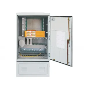
JFDC-144A Fiber Distribution Cabinet
144-port outdoor cabinet for distribution layer networks — supports fusion splice trays, splitter modules, and adapter plates
View Product →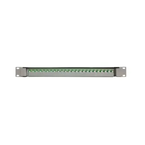
JODF-U3A Fiber Patch Panel
24-port high-density 1U patch panel with LC duplex adapters for data center and central office cross-connect
View Product →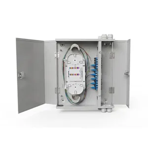
JOTB-48B Fiber Termination Box
48-port wall-mount termination box for FTTH access networks — supports PLC splitters and SC/LC adapter configuration
View Product →Related Articles
Fiber Optic Patch Panel Buyer's Guide
Port count, connector types (LC/MPO), adapter styles, and density options for patch panel selection.
Read Article →
Outdoor Fiber Termination Box Guide
Capacity, IP rating, and wall-mount vs pole-mount options for outdoor fiber termination boxes.
Read Article →
Fiber Splice Closure Installation Guide
Step-by-step field procedure for cable preparation, fiber routing, tray loading, and OTDR testing.
Read Article →References
- ITU-T G.652 — International standard defining singlemode fiber characteristics including mode field diameter, which affects splice loss calculations
- FOA OTDR Testing Reference — How to use an OTDR for fiber link characterization, including bidirectional testing and event analysis
Key takeaway
Fiber termination is a craft. It looks simple — strip, cleave, splice, store. But the quality of each step determines whether your network runs reliably for 25 years or starts failing after the first seasonal temperature swing. Invest in a good cleaver. Keep everything clean. Label as you go. Test at both wavelengths. And always protect the termination inside a properly rated enclosure — whether that's a distribution cabinet, a patch panel, or a termination box. The hardware costs a fraction of the truck roll it saves you.
Related products