Fiber Termination Box Selection Guide: How to Choose the Right Enclosure
By Jergeo Engineering Team | Updated August 2026 · 9 min read

A fiber termination box is the enclosure where the outside plant cable meets the subscriber's drop cable. It sits at the network's edge — on a building facade, a utility pole, inside a stairwell, or mounted in a basement — and its job is to protect fiber splices and adapter ports while giving technicians a structured access point to patch individual subscribers in or out. Choosing the right box at the design stage prevents costly field changes: undersized boxes require adding a second enclosure later, while the wrong material for the environment leads to premature UV degradation, water ingress, or physical damage.
Summary
Select a fiber termination box by matching port capacity to subscriber count (plus 15–20% headroom), choosing an IP rating appropriate to the installation environment, and confirming that the shell material, connector type, and cable entry direction all align with the deployment scenario. Indoor boxes can use ABS or plastic at IP54; outdoor boxes need IP65 minimum with SMC, PC+ABS, or steel construction.
This guide walks through the parameters that matter when specifying a fiber termination box for any FTTH, FTTB, or campus deployment. Product examples reference the Jergeo JOTB series (2-port through 192-port models) because they illustrate the full range of selection trade-offs, but the decision framework applies regardless of manufacturer.
Application scenarios: where fiber termination boxes are deployed
Fiber termination boxes appear at the boundary between the fixed distribution network and the flexible subscriber drop network. The exact installation location determines the box type you need:
Indoor installations
Inside buildings — stairwells, basements, telecom closets, equipment rooms — termination boxes operate in controlled environments. Temperature is regulated, rain is not a factor, and physical access is easy. These conditions allow lighter materials (ABS plastic, thin-gauge metal) and lower IP ratings (IP54). Indoor boxes typically serve 8 to 48 subscribers in an MDU or office building.
Outdoor wall-mount installations
Mounted on building facades or exterior walls, these boxes face direct rain, UV radiation, and temperature swings from −40°C to +65°C. They require IP65 minimum and UV-stabilized materials. Wall-mount is the most common outdoor configuration because it gives technicians the best working ergonomics — the box sits at chest height, and the door opens flat against the wall.
Outdoor pole-mount installations
For aerial fiber networks, termination boxes mount directly on utility poles using stainless steel banding or adjustable bracket arms. Pole-mount boxes must be compact and lightweight — typically 2-port to 12-port models — because larger enclosures create excessive wind load on the pole. Cable entry comes from the top (for aerial drop) or the bottom (for underground feed up the pole).
Underground and pedestal installations
Boxes installed below grade or in ground-level pedestals face the harshest conditions: potential submersion, mud, rodent activity, and corrosion from soil chemicals. These require IP68-rated enclosures with full gasket sealing and gel-sealed cable entries. Underground deployments typically use 12-port to 48-port boxes serving neighborhood distribution points.
Key selection parameters
Port capacity
Port capacity determines the physical size of the box and how many subscriber drops it can serve. The standard capacity tiers are 2, 4, 8, 12, 16, 24, 48, and 192 ports. Here is how capacity maps to real deployment scenarios:
| Capacity | Typical Application | Example Model | Shell Material |
|---|---|---|---|
| 2 ports | Single-home FTTH drop; pole mount | JOTB-2A | ABS |
| 4 ports | Small cluster; 2–4 subscribers | JOTB-4A | Metal |
| 8 ports | Small building; wall mount | JOTB-8A | Metal |
| 12 ports | Standard MDU termination point | JOTB-12A / 12B | Plastic / Metal |
| 24 ports | Medium building or FTTB aggregation | JOTB-24A | Plastic |
| 48 ports | Large MDU or distribution point | JOTB-48B | Cold rolled steel |
| 192 ports | High-density aggregation point | JOTB-192A | Cold rolled steel |
The rule of thumb: count your subscriber drops, add 15–20% spare capacity for future connections, then select the next standard tier above that number. Ordering a box with exactly the ports you need today guarantees a service truck visit when the next subscriber signs up.
IP rating (ingress protection)
The IP rating tells you how well the enclosure seals against dust and water. For fiber termination boxes, three ratings matter:
- IP54: Dust-protected and splash-resistant. Sufficient for indoor installations, sheltered building entrances, and climate-controlled equipment rooms. The enclosure prevents enough dust entry to keep connectors clean, and handles occasional condensation.
- IP65: Fully dust-tight and protected against water jets from any direction. Required for outdoor wall-mount and pole-mount installations exposed to rain. This is the standard outdoor rating for most FTTH deployments worldwide.
- IP67 / IP68: Protected against temporary or continuous submersion. Needed for underground pits, flood-prone areas, and coastal installations where storm surge may reach ground level.
Higher IP ratings add cost and weight because of the gasket sealing and cable gland requirements. Do not specify IP68 for a box that will sit inside an office building — you are paying for protection you will never use.
Shell material
Four materials dominate the fiber termination box market, each with different trade-offs for outdoor life, cost, and physical strength:
| Material | Weight | UV Resistance | Impact | Best For |
|---|---|---|---|---|
| ABS plastic | Lightest | UV-stabilized, good | Moderate | Pole mount, lightweight outdoor |
| SMC (Sheet Molding Compound) | Light | Excellent, 20+ year life | High | Standard outdoor wall mount |
| PC+ABS blend | Light-moderate | Good | High | Outdoor, balanced cost/performance |
| Cold rolled steel | Heaviest | Powder-coated, good | Highest | High-vandalism areas, large enclosures |
For a deeper comparison of these materials and how they perform over 20 years of outdoor exposure, see our fiber cabinet materials guide.
Connector types: SC vs LC vs FC
The adapter panel inside the termination box accepts specific connector types. Your choice must match the rest of the network's connector standard:
- SC adapters: The dominant connector type for FTTH networks worldwide. Push-pull coupling makes it easy for technicians to patch and unplug in tight spaces. Most termination boxes ship with SC/UPC or SC/APC adapters pre-installed.
- LC adapters: Half the size of SC, used in high-density FTTB applications where 24 or 48 ports must fit in a compact enclosure. Common in enterprise and data center environments.
- FC adapters: Screw-on coupling provides vibration resistance. Used in environments with heavy machinery or along railway lines where connectors might shake loose. Less common in standard FTTH deployments.
Some termination boxes accept mixed adapter types — for example, SC on the subscriber side and FC on the feeder side. Confirm adapter compatibility before ordering if your network uses multiple connector standards.
Cable entry options
How cables enter the box determines where you can mount it and how you route the feeder and drop cables. Three entry methods are standard:
- Bottom entry: Cables enter through sealed glands in the base. Standard for underground installations where the feeder cable exits a duct at ground level. Also used for wall-mount boxes where cables run in surface conduit below the box.
- Top entry: Cables drop from above. Used for overhead pole-mount installations where the aerial cable comes down from a span, or where cables enter from a cable tray above.
- Side entry: Cables enter from the left or right panel. Used when cables run horizontally along a wall or through side conduit. Some larger boxes (JOTB-48B with 4 inlet and 4 outlet ports) offer side entry for complex multi-cable routing.
Verify the cable entry direction before ordering. Retrofitting cable glands on site is possible but introduces a potential leak point and costs more in labor than specifying the correct entry configuration upfront.
Splitter compatibility
Modern fiber termination boxes with 12 ports or more can accommodate PLC splitter cassettes. The two standard form factors are:
- 1U cassette: Full rack-unit height, holds a 1×8 or 1×16 PLC module with pigtails. Used in 24-port and larger boxes where internal space permits.
- Half-U cassette: Half the height of a 1U tray, holds a 1×4 or 1×8 module. Used in 12-port boxes and compact enclosures where space is limited.
Smaller boxes (2-port, 4-port, 8-port) typically lack splitter compartments and function as simple pass-through termination points — the fiber passes through a splice and continues to the subscriber's ONT without active splitting at the box.
Indoor vs outdoor selection comparison
The selection criteria shift significantly between indoor and outdoor deployments. Here is a side-by-side comparison:
| Parameter | Indoor Box | Outdoor Box |
|---|---|---|
| IP Rating | IP54 (dust + splash) | IP65 minimum; IP67/68 for underground |
| Material | ABS or thin-gauge metal | SMC, PC+ABS, or cold rolled steel |
| UV resistance | Not required | Required — 20+ year outdoor life |
| Temperature range | 0°C to +40°C typical | −40°C to +65°C |
| Cable sealing | Simple grommets | Worm-gear clamps or gel-sealed glands |
| Mounting | Wall mount (screws to drywall/concrete) | Wall mount, pole mount, or strand mount |
Installation method: wall mount, pole mount, or rack mount
The installation method constrains which boxes you can use:
- Wall mount: All termination box models support wall mounting. Smaller models (up to 24 ports) mount with simple brackets and expansion bolts. Larger models (48-port and 192-port) require multiple fixing points due to their weight — the JOTB-192A uses 4 expansion bolts and a steel shell that weighs significantly more than plastic models.
- Pole mount: Compact boxes (2-port to 12-port) mount directly to utility poles using stainless steel banding or adjustable bracket kits. Larger boxes need a separate pole-mount bracket accessory because their weight and wind profile exceed what a simple strap can handle. Pole-mount boxes are standard for aerial FTTH networks in suburban and rural areas.
- Rack mount: Termination boxes are generally not rack-mount devices. For rack-based fiber termination in a central office or data center, you need a fiber patch panel or ODF (Optical Distribution Frame) instead. Termination boxes are designed for wall, pole, and pedestal installation in the outside plant.
Common selection mistakes to avoid
After years of field deployment feedback, these are the errors that show up most often:
1. Ordering without confirming cable entry direction
The cable route plan determines whether you need bottom, top, or side entry. If the box arrives with bottom-entry glands but your cables run along the wall horizontally, you must drill new entry points — which breaks the IP seal and introduces a future leak risk. Always match the box entry configuration to the cable routing plan before ordering.
2. Specifying IP65 for an indoor installation
IP65 boxes cost more than IP54 boxes because of the gasket sealing, cable glands, and tighter manufacturing tolerances. If the box goes inside a climate-controlled equipment room, IP54 is adequate. The extra cost of IP65 buys nothing in an indoor environment and adds unnecessary weight and complexity.
3. Ignoring spare capacity
Ordering a 12-port box for exactly 12 subscribers means the next new subscriber requires installing an entirely second box — a second site visit, second set of mounting hardware, second cable run. Adding 15–20% spare capacity at the initial order costs marginally more per box and eliminates the need for a follow-up installation.
4. Mixing connector types within a project
Using SC adapters in some boxes and LC in others across the same FTTH network forces technicians to carry two types of patch cables and test equipment adapters. Standardize on one connector type across the entire project — SC for most FTTH deployments, LC for high-density enterprise applications. Mixed connector types add field complexity and increase the spare parts inventory.
Related Products
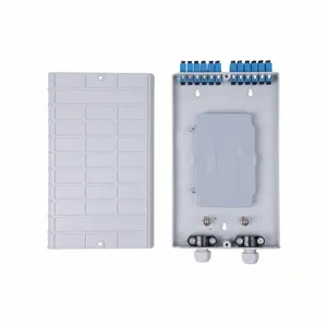
JOTB-12A Optical Terminal Box
12-port fiber termination box for MDU deployments with SC/LC connectors
View Product →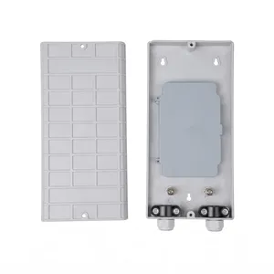
JOTB-24A Optical Terminal Box
24-port outdoor termination box with splitter compartment
View Product →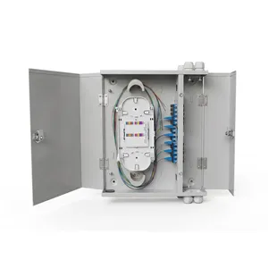
JOTB-48B Optical Terminal Box
48-port high-capacity steel termination box for FTTB aggregation
View Product →References
- The Fiber Optic Association (FOA) — FTTH Reference Guide: selection and installation standards for fiber-to-the-home enclosures
- ITU-T G.984: GPON standard defining the network architecture where termination boxes serve as the final distribution point
Key takeaway
Start with your subscriber count and add 15–20% spare capacity. Confirm the installation environment — indoor, outdoor wall-mount, pole-mount, or underground — to set your IP rating and material. Standardize on one connector type (SC for FTTH) across the entire project. Verify cable entry direction against your routing plan before placing the order. And if you need splitter integration, confirm the box has room for a 1U or half-U PLC cassette before committing to the model.
Related products
Related Articles

Outdoor Fiber Termination Box Guide
Capacity, IP rating, and installation details for outdoor termination boxes.
Read Article →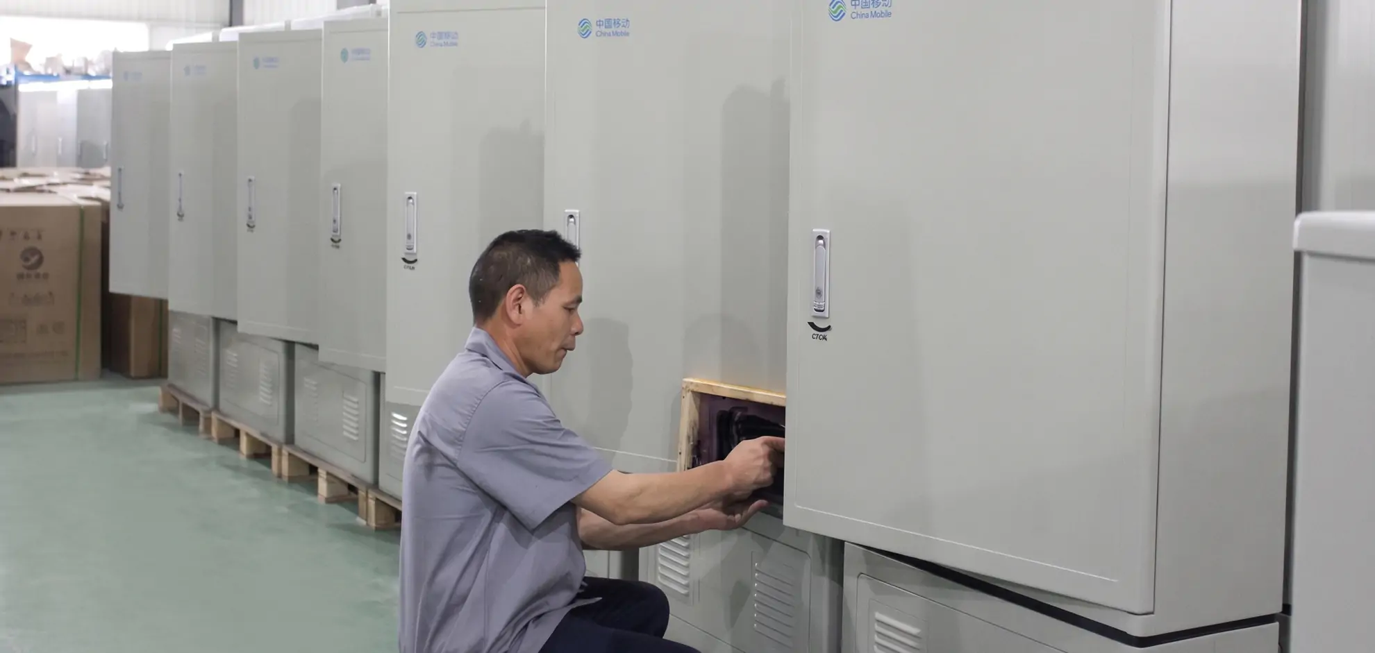
Fiber Distribution Cabinet Buying Guide
For larger-scale deployments: how to choose FDCs from 72 to 1152 ports.
Read Article →
Fiber Cabinet Materials: SMC vs Steel vs ABS
Material comparison for outdoor enclosures — same principles apply to termination boxes.
Read Article →