Aerial Fiber Deployment for FTTH Networks: Field Guide
By Jergeo Engineering Team | Updated August 2026 · 12 min read
Aerial fiber deployment means running fiber optic cables above ground — strung between utility poles, along building facades, or across roads and rivers using self-supporting or messenger-supported cable designs. It is the lowest-cost, fastest-to-deploy fiber access method for greenfield FTTH networks, and the only practical choice in areas where underground duct installation is blocked by existing infrastructure, high water tables, rocky terrain, or dense urban development.
Over the past decade, aerial deployment has become the dominant method for last-mile FTTH rollout across Southeast Asia, sub-Saharan Africa, and Latin America. Operators like Telkom Indonesia, Liquid Intelligent Technologies, and Telefonica have deployed tens of thousands of kilometers of aerial fiber, proving the approach works at scale when engineering standards are followed.
This guide covers the full aerial fiber deployment process — from cable selection and pole assessment through installation, tensioning, weatherproofing, testing, and ongoing maintenance. The procedures apply to both ADSS (all-dielectric self-supporting) and figure-8 cable installations on concrete, steel, and wood poles.
Summary
Aerial fiber deployment for FTTH uses self-supporting cable (ADSS or figure-8) strung between utility poles to deliver fiber to homes and businesses. Choose aerial when underground ducts are impractical — rocky soil, high water tables, existing infrastructure, or budget constraints. Key engineering steps: select cable type by span length, verify pole load capacity, calculate sag-tension per TIA/EIA-222-G, install proper hardware (shackles, thimbles, pole brackets), weatherproof with IP65+ enclosures, and test with OTDR to verify link loss is within budget. Expected deployment cost is $3–8 per meter of route, roughly 40–60% less than equivalent underground installation.

What Is Aerial Fiber Deployment
Aerial fiber deployment is the installation of fiber optic cables above ground level, supported by poles, building attachments, or other elevated structures. The cables used in aerial installations are specifically engineered to withstand outdoor environmental loads — wind, ice, UV radiation, and temperature cycling — without degrading the optical signal.
Two cable designs dominate aerial FTTH deployments:
- ADSS (All-Dielectric Self-Supporting) cable — uses aramid yarn strength members to carry the tensile load. The cable is 100% dielectric — no metallic components — which eliminates induced voltage problems near power lines. Maximum recommended span: 300–600m in normal loading conditions.
- Figure-8 cable — integrates a steel messenger wire in a figure-8 cross-section profile. The messenger carries all tensile load while the fiber unit hangs below. Heavier and less expensive than ADSS, figure-8 is the default choice for spans under 150m and for installations where cost per meter matters more than weight.
Aerial deployment applies to the distribution segment of the FTTH network — from the fiber distribution cabinet (FDC) to the fiber termination point near the subscriber. It is not typically used for backbone or feeder segments where underground duct installation provides better protection for the high fiber-count cables used in those segments.
Aerial vs Underground Fiber: When to Choose Aerial
The aerial-or-underground decision is one of the first engineering calls on any FTTH project. Here is how the two methods compare across the factors that matter most:
| Factor | Aerial | Underground |
|---|---|---|
| Cost per meter | $3–8 | $8–25 |
| Deployment speed | 2–5 km/day (crew of 4) | 0.5–2 km/day (requires trenching) |
| Disruption to area | Minimal — uses existing poles | High — trenching, road cuts, reinstatement |
| Vulnerability | Storms, vehicles, vandalism, trees | Excavation damage, flooding, rodents |
| Maintenance access | Easy — visible, reachable from poles | Difficult — must excavate to access |
| Design life | 20–25 years (cable), hardware varies | 25–40 years (protected environment) |
| Best suited for | Rural, suburban, greenfield, temporary | Dense urban, highways, river crossings |
Choose aerial when: you have access to existing pole infrastructure, the terrain makes trenching expensive (rocky ground, permafrost, swamp), you need fast network activation, or the budget cannot support underground costs. Choose underground when: the route crosses highways or rail lines, the area has high vehicle traffic that threatens pole-mounted infrastructure, local regulations prohibit aerial cable, or you are building a backbone route that must survive major storms.
Many operators use a hybrid approach — underground for the feeder ring, aerial for the last-mile distribution. This is the standard architecture for FTTH networks in Indonesia, the Philippines, Nigeria, and Brazil.
Cable Types for Aerial Deployment
ADSS Cable
All-dielectric self-supporting cable is the preferred choice for aerial FTTH when the route runs near or parallel to power lines. The aramid yarn strength member (typically Kevlar or Twaron) provides tensile strength equivalent to steel at roughly one-third the weight. Because there are no metallic components, ADSS cable can be installed on the same poles as power conductors without risk of induced currents or lightning strike damage to the fiber.
ADSS cable comes in two jacket types: AT (anti-tracking, for installation near power lines with induced voltage above 12 kV/m) and PE (standard polyethylene, for routes away from power lines). AT jacket uses a specialized outer sheath that resists dry-band arcing — a phenomenon where contamination on the cable surface creates leakage currents that erode standard PE jackets over time. Per IEEE 1222, ADSS-AT cable is rated for 1,000 hours of salt fog testing without jacket degradation.
Typical specifications for 48–144 fiber ADSS cable: outer diameter 12–16mm, weight 150–280 kg/km, rated tensile strength 6–12 kN, operating temperature −40°C to +70°C.
Figure-8 Cable
Figure-8 cable gets its name from the cross-section profile — the messenger wire and the fiber tube form a shape resembling the number 8. The galvanized steel messenger (typically 4.0–7.0mm diameter) carries all the tensile load. The fiber unit below contains loose tubes with 12–24 fibers each, surrounded by water-blocking gel or dry swellable powder.
Figure-8 cable costs 30–50% less per meter than equivalent ADSS cable because steel is cheaper than aramid yarn. The tradeoff is weight (300–500 kg/km vs 150–280 kg/km) and the presence of metallic components that require grounding at each pole. Figure-8 is the default aerial cable for telecom-only poles where power line clearance is not a concern.
Self-Supporting Figure-8 Drop Cable
For the final drop from the distribution pole to the subscriber's building, use a lightweight figure-8 drop cable with 1–4 fibers and a small-diameter messenger (2.0–3.0mm). These cables are designed for spans up to 50m and can be terminated directly into an outdoor fiber termination box mounted on the building wall. Drop cable weighs 40–80 kg/km and is supplied on reels of 2–4 km for efficient deployment.
Pole Selection and Mounting Hardware
Pole Types
Aerial fiber runs on three types of poles, each with different load characteristics and hardware requirements:
- Concrete poles — the standard in most developing markets. Pre-stressed concrete, 8–12m length, 200–300mm top diameter. High load capacity (500 kg+ at the mounting point), but heavy and requires crane for installation. Most common in Southeast Asia and Africa.
- Steel poles — tubular or lattice design. Higher strength-to-weight ratio than concrete. Used for tall spans, corner poles with high cable tension, and in areas where transport logistics make concrete poles impractical. Must be hot-dip galvanized to resist corrosion.
- Wood poles — still common in North America, Australia, and parts of Northern Europe. Treated with creosote or CCA preservative. Lower load capacity than concrete or steel (200–400 kg). Must be inspected for rot, insect damage, and ground line deterioration.
Mounting Hardware
The hardware that attaches cable to the pole falls into four categories:
- Band clamps / strap fixtures — stainless steel bands that wrap around the pole and secure the cable anchoring hardware. Used for ADSS cable with helical dead-end fittings. Must be 316 stainless steel in coastal environments.
- Bracket arms (crossarms) — horizontal steel or fiberglass arms bolted to the pole. The cable attaches to the arm end via a shackle and thimble. Standard for figure-8 cable installations. Arm length determines the offset from the pole face (typically 600–1,500mm).
- Pole brackets / D-clamps — bolt-on or weld-on brackets that provide a single attachment point. Used for drop cable anchoring and light cable loads.
- Helical dead-end fittings — preformed wire rods that wrap around the cable jacket and distribute the load over a longer section. Used with ADSS cable to prevent point-load damage to the aramid strength members. Each fitting is sized for a specific cable diameter range.
For detailed installation procedures on pole-mounted enclosures and hardware, see our Pole Mount Cabinet Installation Guide.
Step-by-Step Installation Process
Step 1: Route Survey and Pole Assessment
Walk the entire route before any cable is pulled. Record every pole position, measure span lengths, and note obstacles (roads, rivers, power line crossings). At each pole, check: pole condition (no structural cracks or rot), available mounting positions (clear of power conductors, existing telecom cables), and pole load capacity. If the pole is shared, obtain written authorization from the pole owner. A route survey for a 5 km aerial route typically takes one day with a two-person team.
Step 2: Cable Reel Placement and Payoff
Position cable reels at convenient access points along the route — typically every 2–4 km for ADSS or every 1–2 km for figure-8. Use a powered payoff reel stand that maintains tension on the cable during pay-off to prevent tangling and over-bending. Never pull cable from a reel lying flat on the ground — this twists the cable and damages the fiber. The minimum bending radius during installation is 20× the cable outer diameter (for ADSS) or 15× (for figure-8).
Step 3: Stringing the Cable
For short spans (<150m), a ground-based rope throw or hand-line is sufficient to get the pull rope across. For longer spans, use a helicopter, drone, or pneumatic line thrower. Attach the pull rope to the cable via a swivel and pulling eye — never grip the cable jacket directly with a pulling device. Run the cable over pulley blocks at each intermediate pole, then secure the cable in the final position once the span is complete. Maintain a minimum clearance of 4.5m above roads and 3.0m above pedestrian areas per local regulations.
Step 4: Secure Cable at Each Pole
At each pole, install the anchoring hardware — helical dead-end fitting for ADSS, or a D-clamp/shackle assembly for figure-8. The anchoring point must be at the same height on every intermediate pole to maintain consistent sag. At dead-end poles (direction changes >15°, end of line, or every 500m on straight runs), install dual dead-end fittings with a loop of slack cable between them to absorb longitudinal load.
Step 5: Install Fiber Enclosures and Terminate
At the distribution points — where the feeder cable branches to serve individual subscribers — install a fiber distribution cabinet (FDC) on the pole or at ground level. The FDC houses the splice trays and PLC splitters that divide the feeder fibers into distribution and drop fibers. For smaller distribution points near subscriber premises, use an outdoor fiber termination box or a fiber optic splice closure. Jergeo's JFDC-144A and JFDC-288A cabinets are designed for both pole-mount and pad-mount configurations in aerial FTTH networks.
Step 6: Splice and Test
Fusion splice the distribution fibers to the feeder fibers inside the FDC or splice closure. Use color-coded splice trays following the TIA-598-C fiber identification standard. After all splices are complete, test each fiber with an OTDR (optical time-domain reflectometer) from both ends of the link. Record the trace for each fiber and compare against the loss budget. If any fiber exceeds the budget, locate the fault using the OTDR trace distance-to-event reading and re-splice.
Tensioning and Sag Calculation
Getting sag right is the single most important engineering task in aerial fiber deployment. Too much sag and the cable violates ground clearance requirements. Too little sag and the cable overstresses — the tension exceeds the cable's rated strength, causing fiber attenuation increase or mechanical failure.
The standard calculation uses the parabolic cable equation (valid for sag less than 10% of span length):
Sag (d) = (w × L²) / (8 × T)
where: w = cable weight per unit length (N/m), L = span length (m), T = horizontal tension (N)
For a typical 144-fiber ADSS cable weighing 2.0 N/m on a 200m span at 3,000N tension: Sag = (2.0 × 200²) / (8 × 3,000) = 3.33m, which is 1.67% of span length — acceptable.
Tension must be adjusted for temperature. Fiber cables are typically installed at 10–30°C. At the minimum operating temperature (−20°C in temperate climates), cable contraction increases tension by 15–25%. At the maximum operating temperature (+60°C in direct sunlight), cable expansion increases sag. Design the installation tension so that at both temperature extremes, the cable remains within its rated tension limit and maintains minimum ground clearance.
Use a tension meter (dynamometer) during installation to verify the installed tension matches the calculated value. For ADSS cable, attach the meter between the dead-end fitting and the pole anchor. For figure-8 cable, measure tension on the messenger wire using a clip-on load cell.
Weatherproofing and Environmental Protection
Aerial fiber hardware is exposed to the full range of outdoor conditions — rain, UV radiation, temperature cycling, salt spray (in coastal areas), and industrial pollution. Weatherproofing failures cause 60–70% of all aerial fiber network outages, according to field data from operators in tropical climates.
Enclosure IP Ratings
Every fiber enclosure in the aerial plant — FDC, splice closure, termination box — must be rated IP65 minimum for tropical installations, or IP68 for locations subject to flooding or heavy driven rain. The IP rating means: dust-tight (first digit 6) and protected against water jets from any direction (second digit 5) or protected against continuous immersion (second digit 8). For detailed enclosure selection guidance, see our Outdoor Fiber Termination Box Guide.
UV Protection
Standard polyethylene cable jackets degrade under UV exposure at a rate of approximately 0.1mm per year in tropical sunlight. A 2mm jacket therefore provides 15–20 years of UV protection. For longer design life, specify cable with UV-stabilized black PE compound containing 2–3% carbon black. All pole-mounted enclosures must be manufactured from UV-stable materials — SMC (sheet molding compound) with Class A surface finish, or 304/316 stainless steel with powder coat.
Lightning and Surge Protection
Although ADSS cable is dielectric, the poles and hardware in an aerial network are not. Every pole with metallic hardware should be grounded to earth with a ground resistance of less than 10 ohms, per ITU-T K.25. At poles near the central office orOLT site, install gas discharge tube (GDT) surge arresters on any metallic cable members entering the FTTH network enclosure.
Vegetation Management
Trees growing into aerial fiber cable cause physical damage to the cable jacket and create maintenance nightmares. Maintain a minimum 1.5m clearance between cable and any vegetation on both sides. In tropical growth zones, schedule vegetation trimming twice per year — once before the wet season and once after. Document clearance distances during route survey and flag fast-growing species for more frequent attention.
Testing and Commissioning
Before the aerial fiber link goes live, every fiber must be tested to verify it meets the loss budget. The loss budget for a typical FTTH distribution link (OLT to ONU) is 28 dB for GPON and 32 dB for XGS-PON, but only 18–22 dB is allocated to the outside plant — the rest is reserved for connector loss at the OLT and ONU ends.
OTDR Testing
Test every fiber from both directions using an OTDR at 1310nm and 1550nm wavelengths. The OTDR trace should show: a clean launch pulse, smooth fiber attenuation (0.35 dB/km max at 1310nm for G.652D fiber), low-loss splice events (0.05 dB per fusion splice typical), and a clean end-of-fiber reflection. Any spike, reflection anomaly, or high-loss event indicates a problem that must be investigated before the link is commissioned.
Insertion Loss Testing
Use a light source and power meter (LSPM) to measure end-to-end insertion loss at 1310nm and 1550nm. The LSPM result is the definitive loss measurement — it includes all fiber attenuation, splice loss, and connector loss in the link. The result must be within the allocated outside plant loss budget. If the LSPM measurement disagrees with the OTDR-derived loss by more than 0.5 dB, re-test both instruments with a reference launch cable to verify calibration.
Documentation
Record the following for every aerial fiber link: OTDR traces (both directions, both wavelengths), LSPM insertion loss values, splice matrix (which fiber was spliced to which), GPS coordinates of every pole and enclosure, and cable reel numbers with fiber color codes. This documentation becomes the baseline for future maintenance and fault location.
Maintenance and Troubleshooting
Aerial fiber networks require more active maintenance than underground networks because the plant is exposed to weather, vehicles, vegetation, and human activity. Build a maintenance program around these activities:
Routine Inspection (Quarterly)
- Walk or drive the route and visually inspect cable, poles, and hardware
- Check for loose hardware, corroded fittings, damaged cable jackets
- Verify ground clearance has not decreased due to cable stretch or pole lean
- Trim vegetation encroaching within 1.5m of cable
- Inspect FDC and enclosure seals — replace gaskets showing cracks or compression set
Storm Patrol (Within 24 Hours of Event)
After any wind event exceeding 80 km/h, ice storm, or major lightning event, dispatch patrol crews to inspect the affected route section. Priority checks: downed cable, broken poles, displaced hardware, and cable contact with vegetation or power lines. Do not touch any cable that may be in contact with a power conductor — treat it as energized until verified otherwise.
Fault Location and Repair
When a subscriber reports fiber outage, use the OLT's built-in fiber monitoring (if available) or dispatch a technician with an OTDR. The OTDR locates the fault distance from the test point with ±1m accuracy. Cross-reference with the route documentation to identify the likely pole or span. For cable breaks, install a temporary above-ground joint using a fiber optic splice closure (such as Jergeo's JFSC-T288A dome closure or JFSC-L144A inline closure) and schedule a permanent cable replacement during the next maintenance window.
Cable Re-Tensioning
ADSS cable with aramid strength members loses 5–10% of initial tension over the first 5 years due to creep in the polymer matrix. After 3–5 years, measure sag at 3–5 representative spans and compare with original installation records. If sag has increased by more than 15%, re-tension the cable using a come-along and tension meter, bringing it back to the original design sag value. Figure-8 cable with steel messenger shows minimal creep and rarely needs re-tensioning.
Common Aerial Deployment Mistakes
Skipping the route survey
Teams that start stringing cable without walking the route first discover problems mid-installation — poles that cannot carry load, spans too long for the cable type, clearance violations. A one-day survey prevents a week of rework.
Using PE-jacket ADSS near power lines
Standard PE jacket ADSS installed within 2m of a power conductor will develop tracking damage within 1–3 years. The leakage current burns channels into the jacket, eventually exposing the aramid strength members. Always specify ADSS-AT (anti-tracking) jacket for routes near power lines.
Ignoring temperature compensation
Cable installed at maximum sag on a hot afternoon may violate ground clearance on a cold morning when the cable contracts. Always calculate and verify sag at both the minimum and maximum operating temperatures for your climate zone.
Over-tensioning to reduce sag
Pulling cable tighter than the design tension to achieve less sag overstresses the fiber. The fiber inside the cable has a maximum strain limit of 0.2% during installation (0.05% during operation, per ITU-T G.652). Exceeding this causes permanent attenuation increase. Use a tension meter — never guess.
Related Products
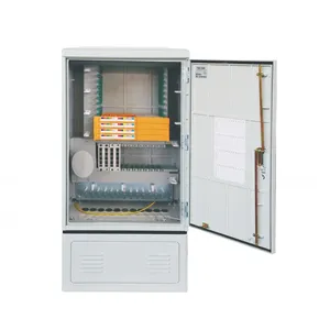
JFDC-144A Fiber Distribution Cabinet
144-port outdoor cabinet for aerial FTTH distribution points, supports pole mount and pad mount configurations
View Product →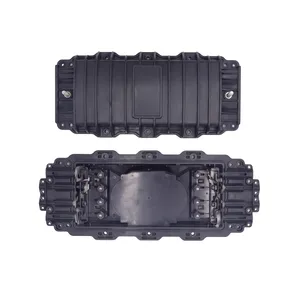
JFSC-T288A Fiber Dome Splice Closure
288-fiber dome closure with IP68 rating for aerial cable jointing and emergency repair
View Product →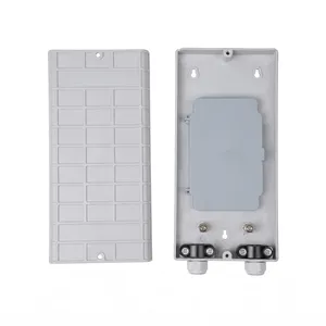
JOTB-24A Fiber Termination Box
24-port outdoor termination box for subscriber drop cable termination in aerial FTTH networks
View Product →Related Articles

Pole Mount Cabinet Installation Guide
Site assessment, mounting hardware, step-by-step installation, and weatherproofing for pole mount fiber cabinets.
Read Article →
Outdoor Fiber Termination Box Guide
Capacity, IP rating, wall-mount vs pole-mount, and connector options for outdoor termination boxes.
Read Article →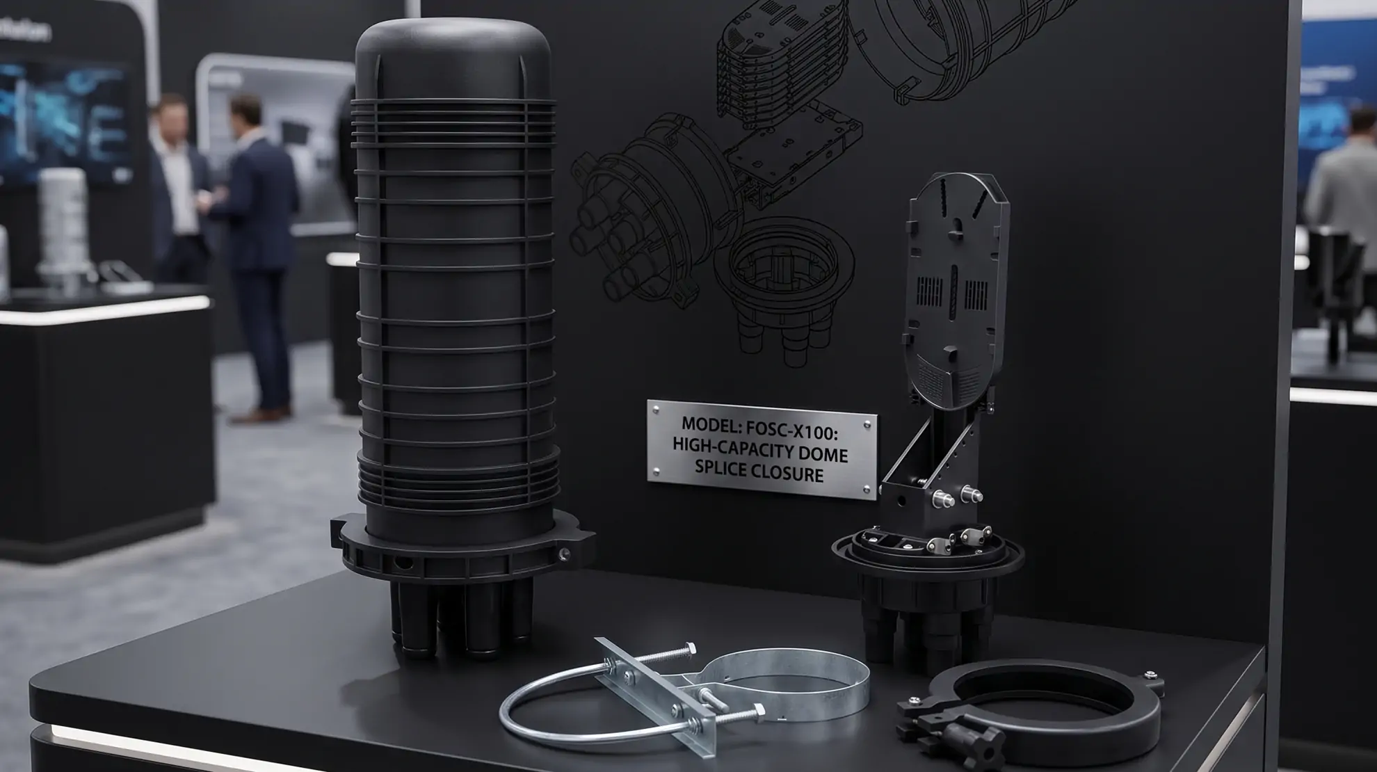
Fiber Optic Splice Closure Guide
Dome vs inline closures, capacity selection, sealing methods, and IP68 protection explained.
Read Article →References
- FOA Reference Guide to OSP Installation — The Fiber Optic Association's reference on outside plant installation practices for aerial fiber
- IEEE 1222 — Standard for All-Dielectric Self-Supporting Fiber Optical Cable
- ITU-T K.25 — Recommendations for earthing and bonding of telecommunication installations
- TIA/EIA-222-G — Structural Standards for Steel Antenna Towers and Antenna Supporting Structures (sag-tension calculations)
Key takeaway
Aerial fiber deployment works when the engineering fundamentals are right. Walk the route before you order cable. Select cable type based on actual span lengths and loading conditions — not what the last project used. Calculate sag at both temperature extremes. Use a tension meter during installation, not guesswork. Seal every enclosure to IP65 minimum. Test every fiber with OTDR before the link goes live. And plan for maintenance from day one — aerial fiber is cheaper to install than underground, but it costs more to keep running. Budget for quarterly inspections, annual vegetation management, and re-tensioning at the 5-year mark.
Related products